Vive Tracker Documentation Update

Vive Tracker Documentation Update

New Information

Following extensive correspondence with HTC, I’ve updated my public documentation of the Vive Tracker.  Due to others already linking to the original documentation page, I’ve decided to keep that URL as the primary and up-to-date source of information.  If you for whatever reason need to reference the out-dated documentation, I’ve archived it at this link.

Upcoming Posts

The next couple of posts will be focusing in on how the development of Talaria has been progressing over the past many months (we’ve been busy!).  After a bit of retrospective, I’ve got some really exciting development to share with you, from completed prototypes of custom SteamVR Tracked objects to DIY capacitive force sensors!  As always, feel free to email me with any questions, or toss some comments on this page down below :)

Vive Tracker – (Relatively) Maintained Documentation

Vive Tracker – (Relatively) Maintained Documentation

*  *  *  *  *  *  *  *  *  *  *  *  *  *  *  *  *  *  *  *
REDDIT USER /U/MATZMANN666 HAS CREATED AN ARDUINO LIBRARY, SEE BOTTOM OF POST FOR MORE INFORMATION
*  *  *  *  *  *  *  *  *  *  *  *  *  *  *  *  *  *  *  *


Hi friends – I’m maintaining this post as I continue working with the Vive Tracker, and will be doing my best to keep up with HTC’s evolving firmware and capabilities.  I focus primarily on USB control of the Tracker, and do not go into interfacing with the pogo pins.  If this is something you all request documentation for, then I’ll take the time to add it.

Please note that if for whatever reason you need to reference my original documentation from March of 2017, it will be archived at this address.  Let’s get into it, shall we?

Below is various levels of abstraction on how I altered the Vive Tracker’s inputs.  Documentation on this page is relevant as of 26 October, 2017.  I started my programming on a breadboarded Atmel AVR (the family of microcontrollers commonly used in Arduino) AT90USB647 chip at 8 MHz and 3.3V with an external 5V power supply to the USB lines.  It should be noted that the Vive Tracker requires a 5V source in order for USB communication to work.  Later, I designed a PCB with the same chip, and now a 3.3-to-5V boost converter to control the Tracker in one condensed circuit.  Additionally worth noting, the Tracker does not externally supply power, which means accessory makers at this time will need to implement a secondary battery into their USB-driving designs.  It would appear that developers can permit the Tracker to charge off the accessory while in-communication over USB, but I have yet to confirm this feature.

1. The Feature Report

See pages 50 – 52 (.pdf file pages 60 – 62) of the USB HID Specification 1.11 for reference on HID Set_Report requests.  Referencing pages 26 – 29 (.pdf file pages 29 – 32) of the HTC Vive Tracker Developer Guidlines v1.5, this is the format for shipping out an HID Feature Report with values specific to the Vive Tracker payloads:

bmRequestType: 0b00100001      // See Page 50 of HID Spec for bit descriptions
bRequest:      0x09            // Value for SET_REPORT
wValue:        0x0300          // MSB=Report Type (0x03, value for Feature report)
                               // LSB=Report ID (0x00, report IDs not used – Page 51)
wIndex:        2               // HTC’s selected Descriptor Index (I think)
wLength:       sizeof(payload) // Size in bytes of the coming payload (Data field, next line)
Data:          {Data_Set_ADDR, Length_of_Following_Data, bData[0], bData[1], … , bData[n]}


MSB = Most Significant Byte, LSB = Least Significant Byte.

Below is an abstracted example for defining an accessory connection and sending a payload declaring the trigger held down halfway and menu button pressed (more on defining bytes below).

bmRequestType: 0b00100001
bRequest:      0x09
wValue:        0x0300
wIndex:        2
wLength:       6
Data:          {0xB3, 3, 0x03, 0x00, 0x00, 0}


bmRequestType: 0b00100001
bRequest:      0x09
wValue:        0x0300
wIndex:        2
wLength:       12
Data:          {0xB4, 10, 0x00, 0b00000100, 0x00, 0x00, 0x00, 0x00, 0x00, 0x7F, 0x00, 0x00}

2. Byte Definitions

The following are HTC’s byte definitions, as outlined by their developer guidelines linked above.  I also add my own notes on the usefulness of various bytes (or lack-thereof).

ADDRESS: 0xB3
UPCOMING_DATA_COUNT (4)
0 – HOST_TYPE (1=PC, 2=PHONE, 3=ACCESSORY)
1 – RESERVED (CHARGE ENABLE, not sure if interfacing with this byte has any visible function)
2 – RESERVED (OS TYPE, TBD)
3 – LPF (Low Pass Filter configuration, 0=184Hz, 1=5Hz, 2=10Hz, 3=20Hz.  Lower frequency configurations ignore slower vibrations of the Tracker IMU, such as from accessory haptics)
{ 0xB3, 4, HOST_TYPE, RESERVED, RESERVED, LPF }


ADDRESS: 0xB4
UPCOMING_DATA_COUNT (10)
0 – NO VISIBLE FUNCTION (TAG INDEX)
1 – BUTTONS:
1.0 – TRIGGER (Following a SteamVR driver update, this value is independent of the analogue trigger byte)
1.1 – GRIP
1.2 – APPLICATION MENU
1.3 – SYSTEM (Yes, it will open the dashboard)
1.4 – TOUCHPAD (Following the same SteamVR driver update, this bit no longer requires TOUCHPAD_CONTACT to be high)
1.5 – TOUCHPAD_CONTACT (Does not require touchpad axis values)
1.6 – RESERVED (But whyyy?)
1.7 – RESERVED
2 – TOUCHPAD_X_LSB (LSB = Least Significant Byte)
3 – TOUCHPAD_X_MSB (MSB = Most Significant Byte)
4 – TOUCHPAD_Y_LSB (LSB)
5 – TOUCHPAD_Y_MSB (MSB)
6 – NO VISIBLE FUNCTION (Technically TRIGGER_LSB, this byte is irrelevant because SteamVR only accepts an 8-bit analogue trigger value and therefore this byte is ignored)
7 – TRIGGER (Technically TRIGGER_MSB, values remain unaffected by TRIGGER button)
8 – RESERVED (Technically BATTERY_LSB, we don’t have access to these bytes)
9 – RESERVED (Technically BATTERY_MSB)
{ 0xB4, 10, 0x00, BUTTONS, PAD_X_LSB, PAD_X_MSB, PAD_Y_LSB, PAD_Y_MSB, 0x00, TRIGGER, RESERVED, RESERVED }


3. Library Interfacing

USB protocols are not something you can just throw together in an afternoon – you’re going to want a library to handle all that overhead (Trust me, this is coming from someone that would rather write their own scripts for basic math functions so everything is in my control – you’re going to want that library).  For the code snippet below, I used the Lightweight USB Framework for AVRs (LUFA) library by Dean Camera, building upon the GenericHIDHost demo found in …\LUFA 151115\Demos\Host\LowLevel\GenericHIDHost; coded in C++.

First I edited the makefile to reflect my chip.  This blog post by Joonas Pihlajamaa really helped me get started.  Below are the values I changed:

  MCU = at90usb647
BOARD = USER
F_CPU = 8000000


I then went into GenericHIDHost.h and removed any references to on-board LEDs or a serial output monitor, as my custom board did not have a definitions file for these things.  Then within GenericHIDHost.c, this was the main function to perform the same task that was described at the end of Section 1 of this post:

int main(void)
{
.   SetupHardware();
.   GlobalInterruptEnable();
.
.   for(;;)
.   {
.       uint8_t payload0xB3[6] = {0xB3, 3, 0x03, 0x00, 0x00, 0};
.       uint8_t payload0xB4[12] = {0xB4, 10, 0x00, 1 << 2, 0x00, 0x00, 0x00, 0x00, 0x00, 0x7F, 0x00, 0x00};
.
.       WriteNextReport(payload0xB3, 0x00, REPORT_TYPE_FEATURE, 6);
.       USB_USBTask();
.
.       WriteNextReport(payload0xB4, 0x00, REPORT_TYPE_FEATURE, 12);
.       USB_USBTask();
.   }
}


This is the bare-bones firmware I needed on my AT90USB647 to get the Tracker to work reliably.  I can assure you it is far from clean.  For example, you do not need to send the 0xB3 payload every time you update data; only once after the initial device enumeration handshake completes.

The other code I had to change was in the LUFA Library was in the function WriteNextReport at the end of GenericHIDHost.c.  Apparently wIndex was set to 0 by default, however HTC’s Vive Tracker requires wIndex to be 2 (this was the missing puzzle piece for weeks when the Tracker was first released!  Change one number and everything finally works; what a feeling)

USB_ControlRequest = (USB_Request_Header_t)
{
.bmRequestType = 0b00100001,
.bRequest      = 0x09,
.wValue        = 0x0300,
.wIndex        = 2,
.wLength       = ReportLength,
};

4. A Low(er)-Level Look

Solely from picking apart Dean’s library, these would seem to be the primary steps that need to be performed in order to successfully communicate with the Vive Tracker:

– Initiate USB as host
– Enumerate the attached USB device
– Read and process the device’s configuration descriptor
– Set the device to its initial configuration (Dean remarks that it’s unlikely to have more than one configuration)
>   bmRequestType: 0b10000000
>   bRequest: 0x09
>   wValue: 1
>   wIndex: 0
>   wLength: 0
>   Data: NULL
– At this stage, all the setup is now complete!
– To send a report:
>   Prepare the bus/pipe
>   Feed it the header (bmRequestType, bRequest, wValue, etc.)
>   Feed it the datastream (starting with {0xB_, etc.} )
>   Return the bus/pipe to its initial state
– Perform any other needed USB host tasks


This section isn’t 100% solidified for me, simply because Dean did such a great job at constructing this library that once I was able to format the payload correctly for the Tracker, I had no more need to dive into the low-level for troubleshooting.  If you’re using AVRs for your microcontroller, I highly recommend Dean’s LUFA library!

I am by no means proficient in USB HID communications, but if you run into any road blocks then feel free to reach out to me, perhaps I’ll be able to offer some advice as a result of my own troubleshooting.

I made note of this at the top – if you think that it would be valuable for me to develop this into an library for USB Host-capable Arduino boards, please comment your interest below.  It could definitely help out if you explain what you would hope to use said library to do with the Vive Tracker.

EDIT: Reddit user /u/matzmann666 has wonderfully created a library for the Arduino Due ARM-based microcontroller!  Check out their GitHub page here: github.com/matzman666/USBHost

And lastly, I’d like to send a thousand thanks to Dario Laverde from HTC.  He was a great help in troubleshooting a lot of the feature report content, and I wouldn’t have Vive Trackers to work with if it weren’t for him.  Thank you, Dario!

Alright, that’s all I’ve got for this documentation.  Like I said at the top, let me know if there’s aspects about the Tracker that the community needs documentation on, and I’ll look into what I can learn.  I hope some folks out there find this information useful :)

Initial SteamVR Tracking Experimentation

Initial SteamVR Tracking Experimentation

Motion Capturing a Mug in VR

I wanted my first through-and-through project/experiment with SteamVR to be something practical; I tossed around the idea of motion capturing my keyboard or mouse, some headphones, etc. – the usual things that folks want to be brought in to their virtual environment from the real world.  I settled on a mug because of two reasons: 1.) There’s enough unused exterior surface on the mug that I’d have plenty of room to place sensors and the Watchman board, and 2.) It sounded pretty convenient to grab a drink in VR without removing the HMD.  This timelapse shown above was recorded on the 17th of November, 2016, and covers approximately an 8 1/2 hour nonstop development process.  I can shave that time down to at least 2 hours now that I’ve got this run under my belt and know what quirks can be run into.  Once familiar enough, I could see having something hand-made together in 30 minutes being a practical timeline.

Modelling the .STL

So I started out with modelling a replica of the real-world mug in Blender (free and open-source 3D modelling software).  This was my first full-on experience with Blender, so a good chunk of my time was spent learning the interface and following a basic tutorial.  I probably gave this mug way too much fidelity, but hey, I’m proud of the little guy.  Maybe one of these days I’ll look into texturing my models with something that’s more than just UV grid.  More information regarding the render model can be found in my post from Day 3 of Synapse’s SteamVR Tracking training.

Verification Simulation

The HMD Designer simulation software is valuable tool for quantifying the optimization of custom shapes, as well as providing inspiration and validation for sensor placement.  For reference, the Vive controllers have 24 sensors present on them.  This mug uses 14 (a number chosen through a combination of physical limitations, simplicity’s sake, and quick simulation optimization).

Below is a model of the mug, along with some occlusion models:

The reason for these occlusion models was so that the simulation wouldn’t place sensors on or near the handle, inside the mug, or under the mug, as well as to be mindful of the Watchman board’s presence (occlusion models are a separate setting in HMD Designer, yet render the same as the tracked object).

All simulations were pretty similar, but this one felt most systematic and balanced from the batch that I ran:

Those graphs are pretty good!  Remember – the centre of each graph is the negative Z direction, unwrapping the other sides horizontally, and positive/negative Y spanning the top and bottom stretches of the graph.  Feel free to refer back to my coverage of Day 2 of the training for a more thorough explanation of the graphs.  But anyway, the centre of each graph would be the mug’s handle in this context.  These results show that there is more or less manageable optical tracking from all side views of the mug.  I used this placement as a launching point, primarily taking note of the sort of 5-point ‘X’ present on either side of the mug.  And so here’s a shot of the final sensor positions that I calculated into the JSON:

Note the 5-point ‘X’ being a lot more uniform.  An ‘X’ on either side meant using 10 sensors, but also a blind spot in the front and back of the mug.  To improve tracking beyond these 10 points, I set up the minimum number of sensors needed to catch a pose on the front of the mug – 4; and hence the total sensor count being 14.  Check out this post for an in-depth review into what dictates sensor count and positions.

Now obviously there’s a lot of red/orange/yellow in the graphs.  This is 100% not at all a marketable configuration, but it has enough blue/green zones to catch a pose from a front or either side view, and that’s satisfactory enough to move on and give this little experiment a go!  Plus SteamVR does a pretty fine job at being able to solve poses based on the IMU and just 1 or 2 sensors alone once it’s locked down to a known position.  So looking at the Initial Pose Possible graph, it’s clear that a front view or side view will catch a pose with deep blue confidence.  Then from that point, using the Number of Visible Sensors graph, tracking will be able to “survive” from most views that isn’t from above or below.

Again, I’d like to reiterate that a proper prototype should be held to far higher standards than what I’m going for in this run.  This was more so a test for me to ensure that I’m familiar with the SteamVR prototyping process.  This is 10 sensors less than a Vive controller – between that and the fact this was hand-assembled in one night, I think this reliability is pretty OK.

Assembly!

I am a tinkerer, and hardware is my jam.  This is always going to be the most fun part of the design process for me – hands-on development.  Here’s some shots of the final assembly:


Everything is affixed to the mug with pressure sensitive adhesive tape, and for the short-term that stuff holds pretty well.  Any long-term development and you’re going to want an epoxy or something else that has a lot more stick than just a bit of tape.  For reference and scale, the Watchman board is the small square at the bottom centre of the board suite, best seen in the third picture.  The application board is the larger board with the bright light, which the Watchman is plugged into; it also has the USB port and battery plugged in.  Then the third board is the FPGA / sensor breakout, which has all those white connectors that the ribbon wires are connected to.  That board attaches with the other end of the Watchman.  And that little black rectangle sticking out to the left of the mug is the basic antenna for wireless communication.

Calibration and 
Caveats

Again bearing in mind that this was hand-measured and hand-assembled, the calibration and stability of tracking is pretty darn good!  But that’s not to say it’s without problems.  This clip shows how much error can come out of a poor calibration that only uses a small sampling range of tracking data:


And so that was a pretty unacceptable offset.  After quite a bit of troubleshooting (I think it was between the calibration and modelling the .STL that ate away most of my time during this project), thinking the error was an issue with defining the centre of the mug in the JSON file, I concluded that the calibration was the culprit.  Just think – if you want to achieve submillimeter accuracy, your sensors are going to need to be placed with submillimeter accuracy!  Not by eye and hand as was done in this project – they should be in line with where the JSON expects them to be with minimal offset if you want a properly positioned result.  So I moved on to recalibrate using a lot more tracking samples to work with, walking around the whole room so the system had plenty of different perspectives when solving for true sensor placement.  Below is the recalibrated result:


This new result certainly isn’t great, but I’d say it’s pretty acceptable considering how hastily this rig was put together.  Now let’s put it to use.


Having a Drink in VR!

As shown in the timelapse featured at the top of this post – it works!  I was able to see the mug and its render model whenever opening the SteamVR dashboard, and could easily access it for a drink whenever I needed.  But boy, was it terrifying taking that first sip – because of the HMD, I had to angle my head back along with the mug to the point where I was seriously concerned of flooding the headset.  Haha, thankfully such an event did not occur.  But I definitely foresee bottles and straws being a far more common way to drink from within VR in the future.

Oh, and it’s worth noting that the mug is wired in these videos because I made the mistake of plugging my SteamVR USB RF receiver directly into my PC (without a hub), and something they warned us about in the training is that proximity to USB 3.0 ports is a known issue that messes with RF communication.  During the week after this prototyping marathon I was able to sustain stable wireless tracking by plugging into the headset’s extra USB connector (which oddly enough is blue, implying it’s USB 3.0…)

Further Experimentation

The neat thing about making custom SteamVR tracked objects is that they communicate to your PC the same way your Vive controllers (or HMDs) do, so as far as SteamVR and its hosted experiences are concerned, my mug was just a third controller.  If I turned off one of the Vive controllers, then I was able to use my mug in place of it!  Only a few games actually bring in the render model itself (most will replace the render model with something more custom/stylized for that experience), but it was pretty sweet punching beats and petting a robo-dog with a mug, haha.

Another thing to take note of is that when the pin is floating / not connected, the analogue trigger believes it is pulled all the way.  You can see during the video I will grab things accidentally and not be able to let go.  Interesting!

I kept this mug around for a little while, using it during long sessions to keep hydrated without breaking immersion; it was pretty sweet that something I made in one got so much use.  But alas, exposed electronics attached to a vessel that’s host to water probably isn’t the smartest pairing…  Bottom line, I managed to water damage one of the application boards given to us in the hardware development kit.

Whoops.

Thankfully it wasn’t the extremely valuable Watchman board, but still – darn.  I was able to harvest the other application board out of the the reference object / mushroom from the training, but needless to say I didn’t use the mug anymore after that experience.

Next time…

I hope my ongoing documentation of this process is useful/interesting to you all!  Next SteamVR post, we’ll look into exploring 3D printed parts and some early ideas on a prototypical product :)

I love hearing from the community, so I encourage you to join in the discussions down in the comments, or feel free to write me an email via blog@talariavr.com!  ‘Til next time.

SteamVR Tracking License Recap and Answering Questions

SteamVR Tracking License Recap and Answering Questions

Review

First of all, really sorry about the delay here between hardware posts.  This one was stuck in approval for a while and made its way around, ultimately receiving the go-ahead from Valve.  So while it may be a long time coming, hopefully this in-depth review of content will really help those of you interested in the design of SteamVR tracked objects better understand the nuances of sensor placement.  Expect to see a good deal more hardware posts in the coming weeks (I’ve got quite a backlog to push out!)

So again, the training course was great.  As a launchpad, if you want to read over my full experience of it, here are links to Day 1, Day 2, and Day 3 of the training, as well as the category page for the tracking license.

Reviewing over all the content that was learned and experiences had, I’d have to say that the most important takeaway from the course was understanding and optimizing sensor placement.  The math for it is just beautiful.  Below I’ll go ahead and break down what each additional sensor adds to tracking stability:

0 Sensors (Basestation Protocol)
Well, all you have right now is a space that has lasers sweeping through it.  The protocol a single basestation emits goes as follows: an array of infra-red LEDs pulses for a specific length of time.  Then, a vertical fan of infrared light is scanned horizontally through the space, at a field-of-view of 120 degrees, rate of 60 Hz.  After another pulse, a horizontal fan of the same characteristics scanning vertically then follows.  This process is then repeated so long as the basestations have power!

1 Sensor (X- & Y-Position)
Your first sensor will give you an x and y radial coordinate.  So if you think about how a single sensor sees a basestation, it sees the sync pulse and starts its timer.  Then, once contacted by the first sweep, the time signature of this event is saved, and our sensor knows it exists somewhere within the area of that vertical fan at that specific time.  After the second sweep arrives, our sensor can further narrow down its position to be where the time signature positioning of the horizontal and vertical sweeps overlap.  Visualizing this, we now have a single line of potential locations radiating from the basestation.  Our radial x and y coordinates have been established, but our sensor can still reside anywhere on the radial z-axis.

2 Sensors (Z-Rotation)
Next we add a second sensor.  The benefit of this one is that by knowing the x- and y-position of each sensor (which are of a fixed placement apart), we get an understanding for how our object is oriented along the z-axis.  And let me say here that these (and all future) sensors need to be rigidly attached!  Without that, our system will simply know the radial z position for each sensor but no reference for where each sensor is to one another, and therefore not be able to lock down any more pose information.  But a problem still presents itself with two sensors on the object: each sensor could still exist anywhere on that radial z-axis.  Because of that, our object could be anywhere from extremely distant and facing normal to the basestation, or extremely near and severely angled to the basestation.  The sensors would still be hit by the laser sweeps at the same times.  This is referred to as pose translation error.

3 Sensors (Z-Position)
On to a third sensor, let’s first imagine three sensors together in a line.  We’ll still see the same pose translation error as described above; each sensor will still be proportionally related as the angle increases and position grows nearer.  To mediate this, let’s attach that third sensor to be non-collinear to the other two.  Now, when our object angles towards the basestation and gets closer, we would expect to see that third non-collinear point to have a more pronounced offset from the other two.  Using this understanding, 3 sensors can finally lock down our z-position.  Hooray!  But we’re not out of the woods yet.  No matter how precise they’re manufactured, basestations will inherently have a small (VERY small) amount of wobble to them, as well as there being IR-distortions inside the tracking volume (such as heat waves).  Because of this minor error, the current system is not precise enough to discern between 3 sensors that are facing head-on and 3 sensors that are skewed by a few degrees along the x- and y-axes.  This is referred to as pose rotation error.

4 Sensors (X- & Y-Rotation)
So now to the last required sensor; number four.  If our fourth sensor resided in the same plane as the other three, then we would have the same issue with pose rotation error.  To get around that, we pull it out of the plane.  With four non-coplanar sensors, this helps because as an object rotates now, we get the parallax of angular motion, and that parallax really helps eliminate a wide range of possible poses that were present from the inherent basestation error.  We refer to that as establishing the baseline.

>4 Sensors (Occlusion Protection & Redundancy)
Great!  We have a reliable motion-captured object that SteamVR will be happy to use!  But of course the issue still exists of turning the device away / occluding the sensors from a basestation.  For this, we need to be sure that all angles and occlusions are accounted for.  That’s where Valve’s HMD Designer software comes into play (visualizations can be seen in my Day 2 post, as well as in future content).  Additionally, adding more than 4 sensors in the same visible area creates redundancies, and (while it will increase the cost of the device) redundancies can only help maintain even more stable tracking.  The maximum sensors that can be used in the present firmware are 32 sensors on one device, and this device is an HMD with very few inputs.  For a controller with 1 analog and 5 digital inputs (and the x/y serial input of the trackpad), I believe the sensor cap is 28.

So that about wraps up an in-depth review of the SteamVR Tracking system!  Again, my apologies that it took so long to post publicly; really hoping to be in a steady rhythm for this blog now.  Feel free to let me know if any of these points require clarification.

Answering Community Questions

Below are (paraphrased) questions that were raised by members of the community on Reddit, by email, or here on the blog.  If you asked a question through any of these media and it is not featured here, it may be that it was very specific, or covered in great depth in a previous post.  If you don’t personally hear from me sometime in the next week, feel free to ping me with that question again.

Any word on larger tracked volumes / more than 2 lighthouses?
Asked in combination by Lanfeix on Reddit and Bernd K. over email
Valve is always prototyping and testing many ideas, multiple lighthouses certainly being one of them.  As far as licensees are aware, however, no one design has been locked down yet.  It was mentioned at Steam Dev Days that Valve hopes for lighthouse to be as ubiquitous as WiFi in the future, so take that for what it’s worth!

What are other developers working on?  Wireless HMDs, body tracking, modified controllers, etc…
Asked in combination by Ducksdoctor on RedditGuichla on Reddit, and darrellspivey on Reddit
I am not at liberty to disclose any developmental plans for my colleagues from the training.  Regarding the wireless HMD modifications, however, TPCAST was announced as a Vive accessory while we were in training.  And as for body tracking, I can assure you that is a very frequently requested device / suite (and I’m personally working on evolving the Talaria locomotion wearable to include lighthouse tracking; will open up foot-tracking to the masses, plus many other awesome features!  More info on that to come over the next month or so)

What resources are available to the public to prototype for lighthouse?  Will audio/video recordings and documentation ever be made publicly available?
Asked in combination by Mentalyspoonfed on Redditthebigman433 on Reddit, VRGameZone on Reddit, and over email
Anyone is welcome to play around with the technology – Triad Semiconductor sells their TS3633 castellated modules for about $7 a pop, and they have everything on board to sense the IR signal from a basestation and convert it to a digital output.  That being said, without access to the hardware (which comes with the license), you will have no way of communicating that sensor data to SteamVR – you would be required to run motion capture in your own application (but that’s not to say it can’t be done!).  At this time, taking Synapse’s SteamVR Tracking training is required to ensure everyone is properly prepared to develop for lighthouse in these early days of the technology.  In the future, Valve has intentions to make the training and documentation fully available to the public, but that will likely come after this first batch of trainees have enough time to give feedback and work out the kinks.  And I personally was able to take an audio recording of the course, however that is restricted to internal use only.

I thought the magic number of required sensors used to be five – why do you keep saying four?  Is it possible to capture position using just one sensor?
Asked in combination by Mark Hogan on the blog and Bernd K. over email
As stated above, one sensor will let you lock down an x and y radial coordinate, but that sensor could exist anywhere in the radial z direction.  A second sensor locks down your rotation about the z-axis, but again position in the z direction will still be ambiguous (could be anywhere between far away and facing perpendicular to the basestation, or up very close at an extreme angle.  Both sensors will still be hit at the same times).  Adding in a third (non-collinear) sensor will allow you to establish the z-position of your device.  Then the reason for a fourth (non-coplanar) sensor is to aid in solidifying x- and y-axis rotations, as without the parallax of that fourth sensor it is very difficult to determine minor changes in x- and y- rotation.  As for why Valve used to say that you needed five to lock down a position, we don’t really know.  Stable tracking is successfully achieved with four – perhaps it was a safety measure for redundancy.

How do tracked objects know which lighthouse hit it?
Asked by Mark Hogan on the blog
The sync pulse from each base station lasts for a different amount of time depending on which channel that base is set to.  The IR sensors on each device can see this difference and it acts as a means of identification for each lighthouse.

What’s the difference between a ‘chiclet’ and the TS3633-CM1?
Asked by Bernd K. over email
Both modules are functionally the same.  The chiclet provided to developers by Synapse is a more compact, dual-sided design that has a flex cable connector on it.  The CM1 is single-sided and pins out to castellations.

What’s going to be covered at the SXSW SteamVR Tracking session?
Asked by VRGameZone on Reddit
This session will be an overview of what will be covered by the training.  Pretty much all the content we learned in Day 1 (not the full training).  To my understanding, there is no need to sign up; simply attend!

So that’s everything you folks have asked me so far!  I hope the community finds the information here useful.  If you have any more questions, feel free to throw them to the comments, or email me at blog@talariavr.com.  I’ve been quite busy this past month, so get excited for what’s coming next!

Hardware Update and VR Storyboard

Hardware Update and VR Storyboard

Hardware Update

Sorry it’s been a while since my last post, everyone – but fear not, I have been busy!  We’re just waiting on Synapse to review the SteamVR Tracking license recap and community questions post once they return from their Thanksgiving holiday.  Expect it this week!  Also look forward to seeing my janky prototyping skills sometime soon :)

In the meantime, I suppose I’ll share the development process of a VR storytelling experience I’m working on.  I’m callin’ this one “Somniat.”

Viveport Developer Awards

While I can talk about VR design for days, I haven’t had the chance / made the time to design a proper experience yet.  However, with the Thanksgiving holiday I found myself in a week without obligations, and HTC just so happens to be hosting an awards showcase called the Viveport Developer Awards (VDAs) that doesn’t close until 30 November.  I’ve been working on a storyboard for an interactive narrative over the past month, and so I figured I’d try to assemble it into a functional experience over these ~10 days (as of really solidifying the storyboard).  It’ll be like a game jam, but longer! …and lonelier.

Also being completely transparent, there’s a good chance this experience won’t be able to be considered for the VDAs.  I believe it needs to be published by 30 November, and the Viveport Developer Guide states that developers should give the submission process a 2 week overhead; plus there’s always unforeseen hiccups in the development workflow.  Whether or not it’s eligible, I’m still excited to bring this experience to life and hear what users have to say about it.

But hey!  I’m holding onto that good old fashioned “what if” for some extra motivation.

Somniat

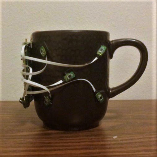
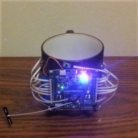
So as a brief preface, I’ve learned that when I create something, I really like to know every bit of how that thing works, inside and out.  Because of that, I like to start from the ground up in a lot of situations (this is why the Talaria locomotion wearable prototyping environment is made entirely of primitives – I wasn’t familiar with any formal 3D modelling at the time, and still wanted to know everything that was going into the project).  I suppose it’s tied to a love of learning, and also probably a bit of perfectionism.  Either way, because of this mindset I plan on very minimally using outside assets in this project.  I would love to do all the scripting, modelling, audio, interaction, story, and so on internally.  This isn’t because I think I can do it “better” than others already have (I can assure you that anyone with a focus in any of those aforementioned areas could easily surpass what I create), but because I’m eager to experience the process of creating an experience from start to finish and putting it all together, performing all steps in between.  Plus I get to create an experience for other human beings.  How cool is that?!  Again, this may not be a practical approach considering the given time frame, but nevertheless I am looking forward to what I will learn.

So Somniat is going to be a interactive storytelling experience.  I’m really drawn to the possibilities VR has as a storytelling medium, and this project is a way for me to start exploring what is possible.  Going in, I know there are a few things I would like to avoid or focus on: I don’t want this to be a passive experience.  I want the user to be the main character of a plot, and not to watch the plot happen to somebody/something else.  I also love suspension of disbelief and experiencing the surreal.  I find surreal experiences in VR to be so profound; it’s like unlocking all the imagination we had when we were kids and telling our brains it’s real again.  And that leads to my last hope – I want my users to have a return to innocence; to be kids again.  I fear that by simply living our lives we easily lose sight of all the imagination, spontaneity, and joy that followed us daily through childhood.  I want to try and reconnect with those feelings, even if it’s just a little bit.

Since this is due to be such a quick turnaround, if you’d rather experience the content first hand without spoilers, feel free to come back to the rest of this post once the release is public.

Let’s get into the storyboard!

Storyboard

Behold!  My storyboarding wall!

storyboarding-wall

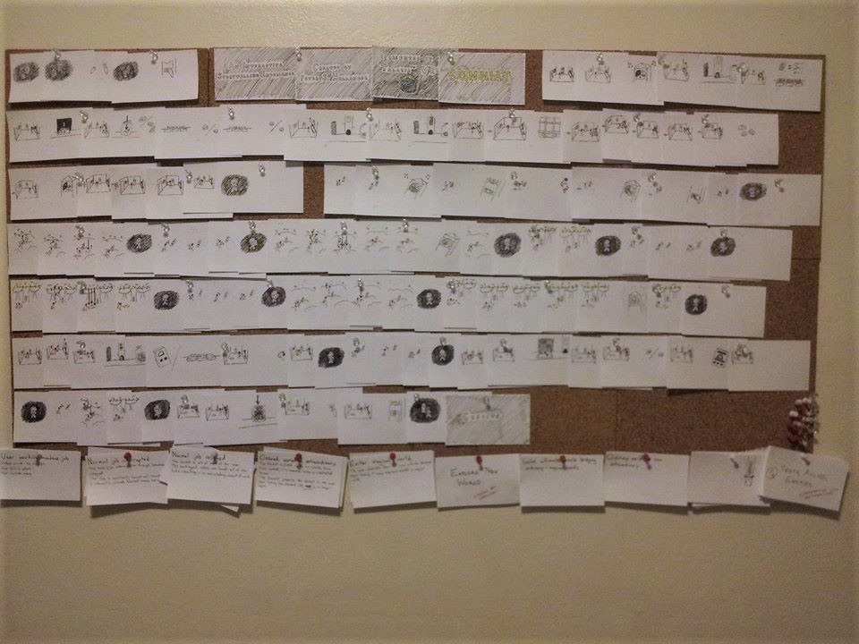
That’s 110 cards pinned up.  It was a really fun adventure watching all those doodles come together into a coherent story.

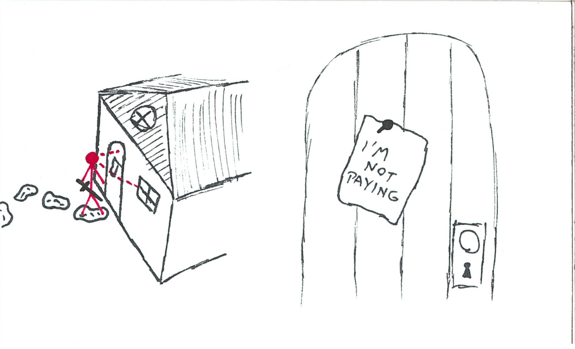
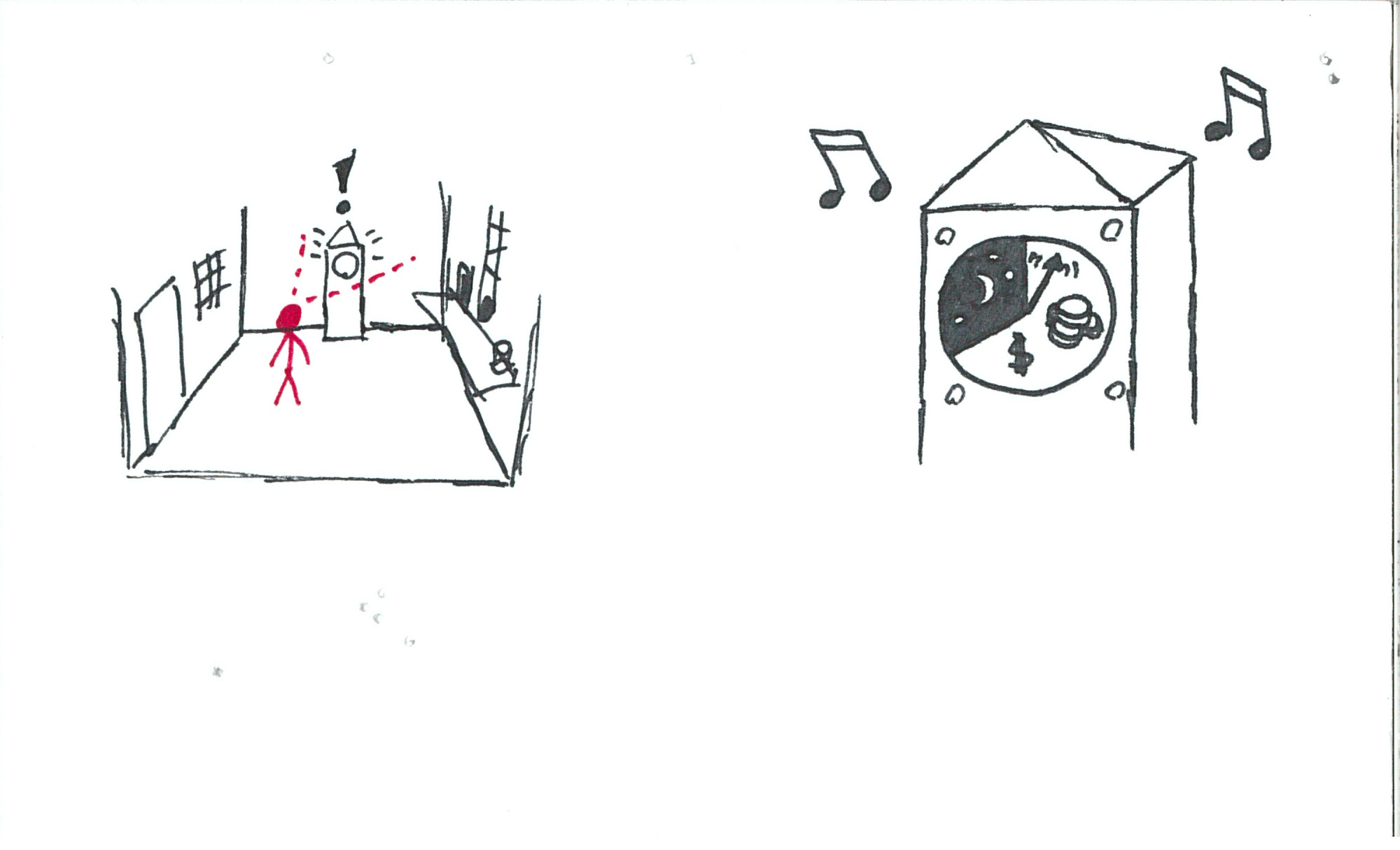
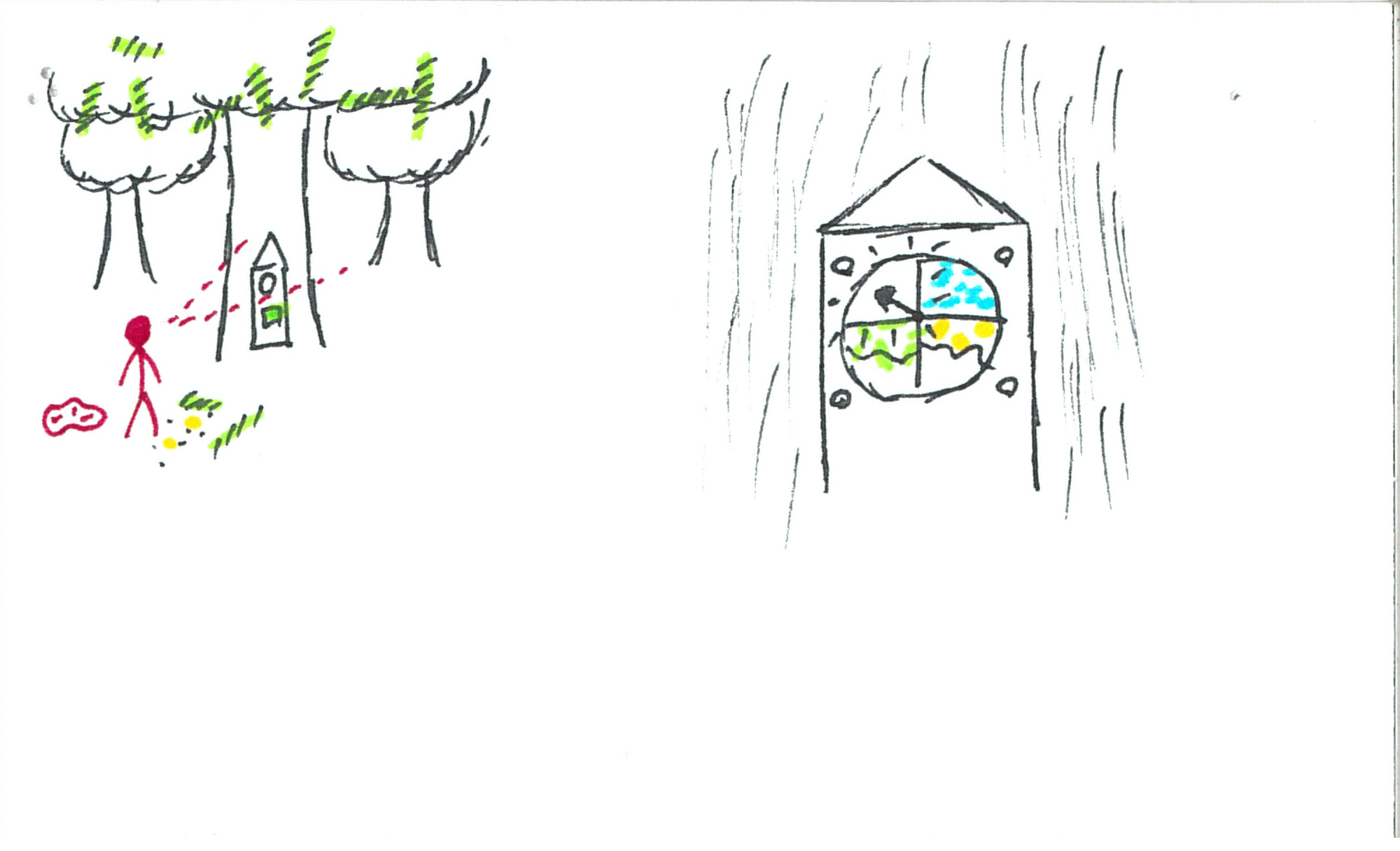
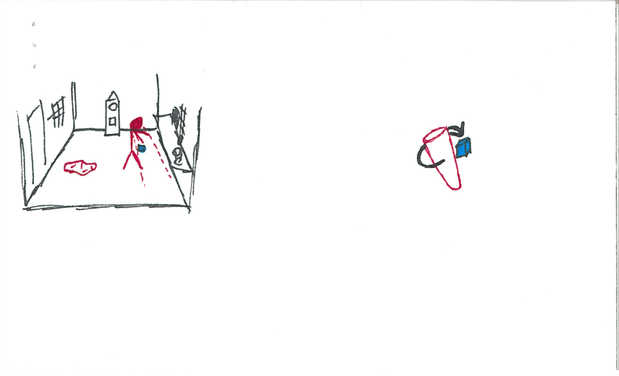
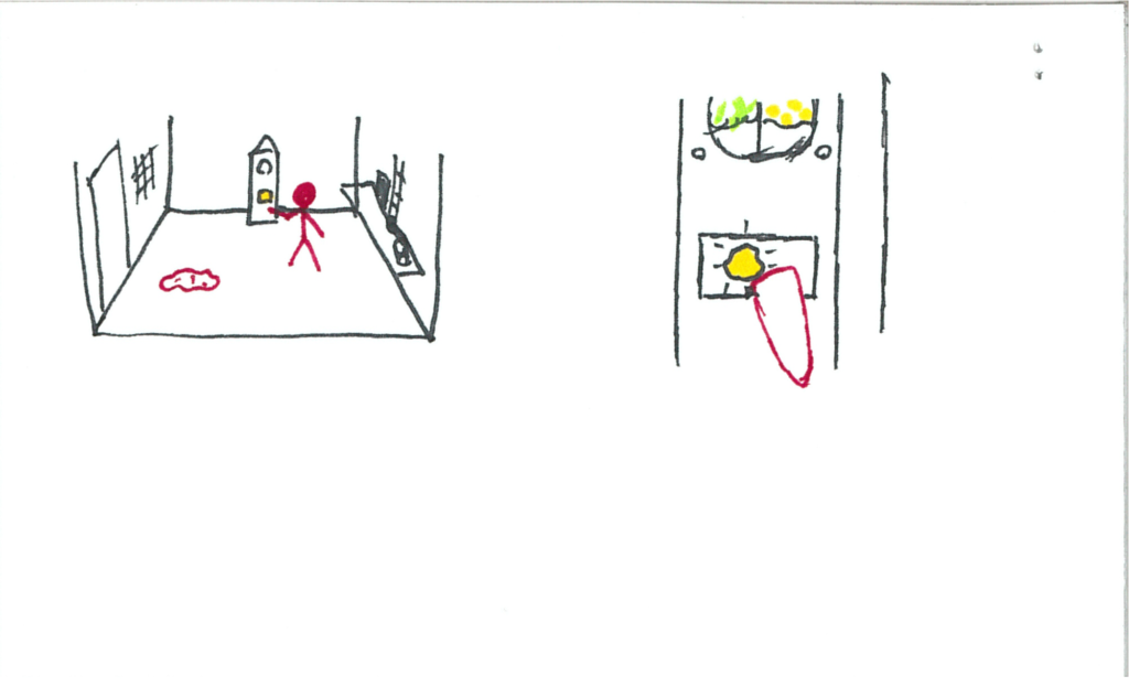
Taking inspiration from Vincent McCurley’s “Storyboarding in Virtual Reality, I’ve created a format for storyboarding VR of my own.  Below is an example:

 vr-storyboard-example

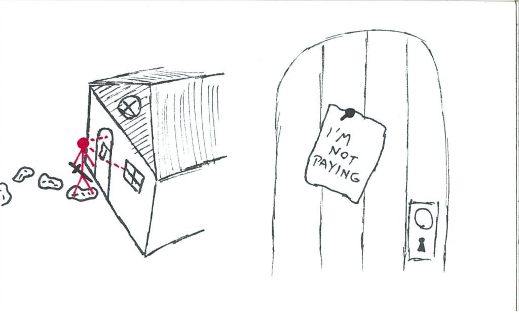
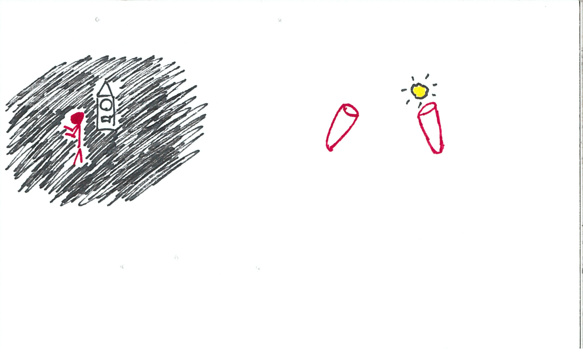
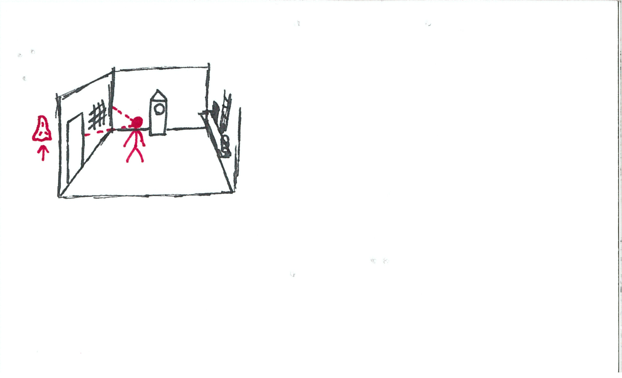
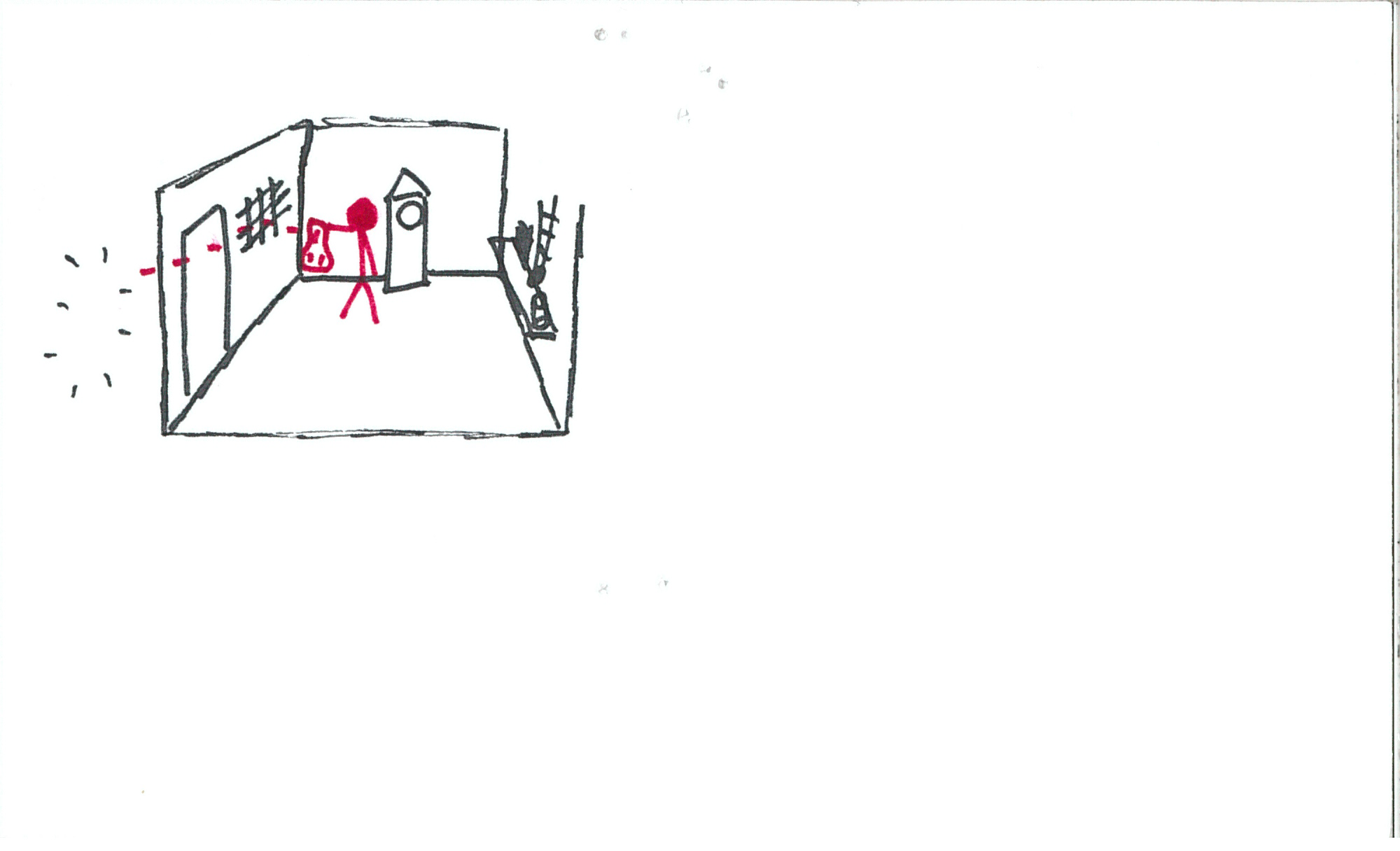
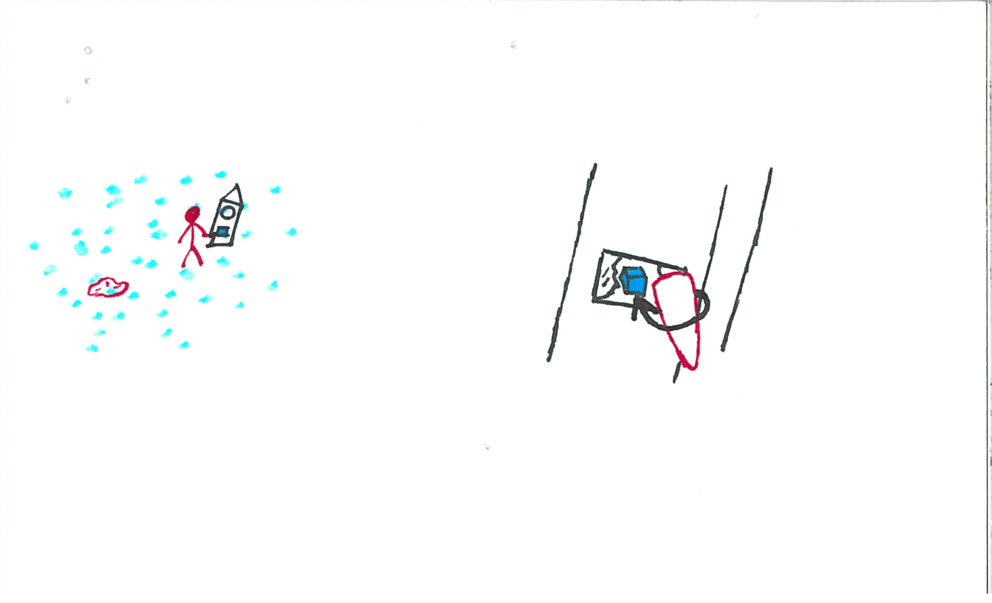
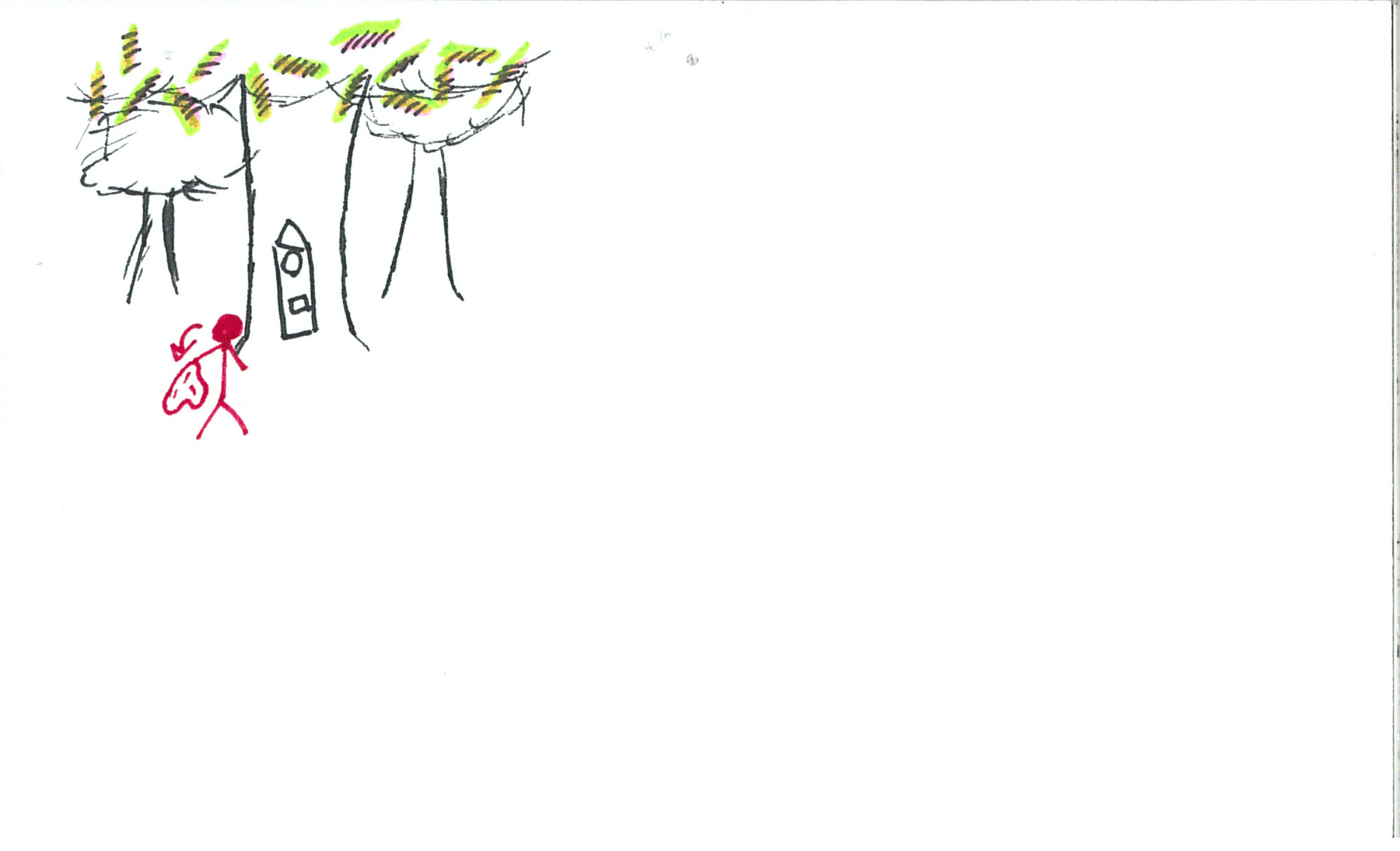
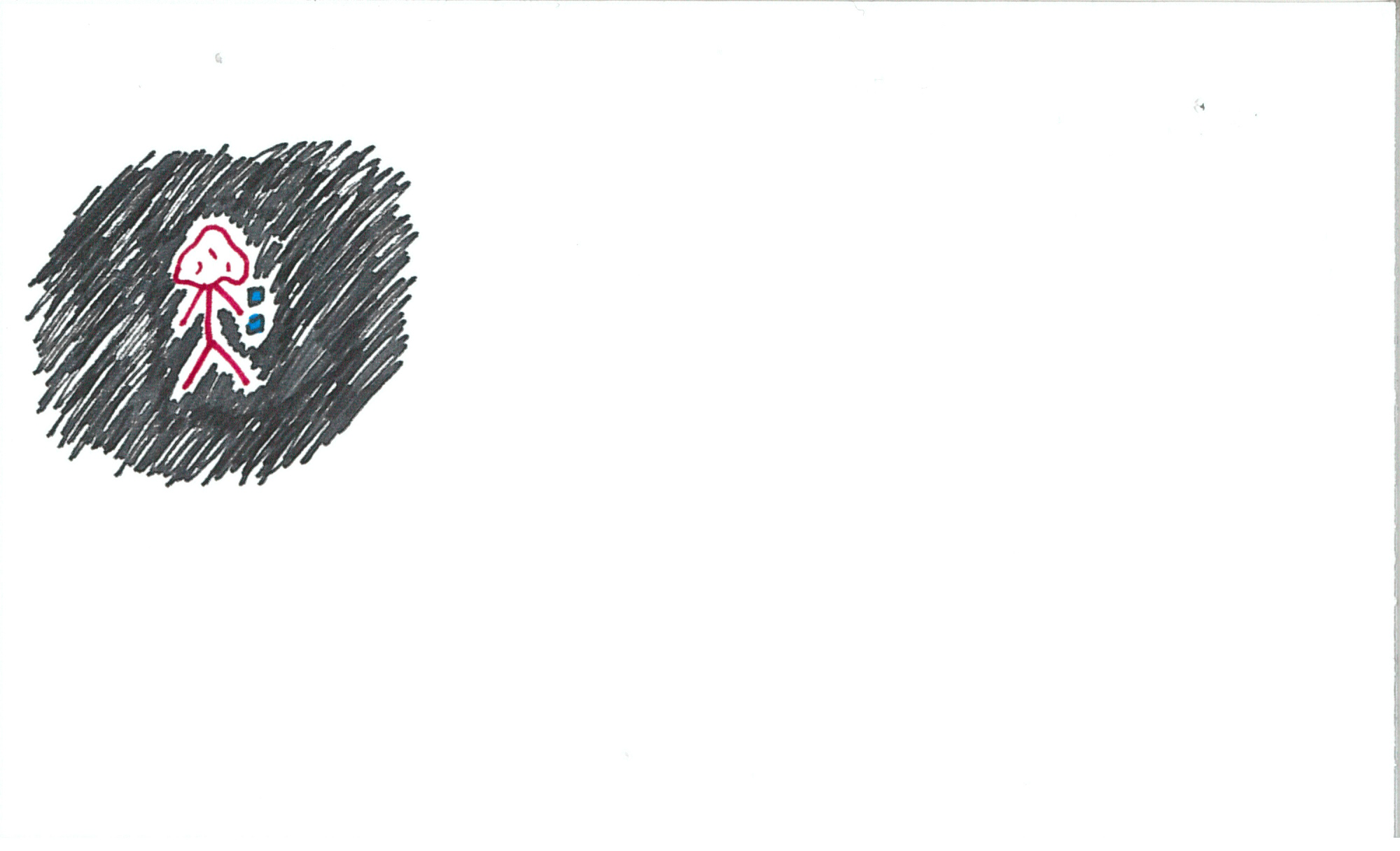
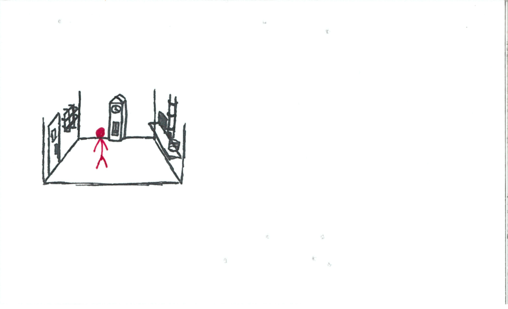
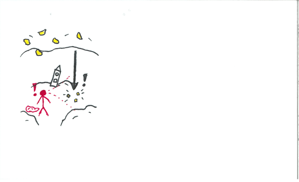
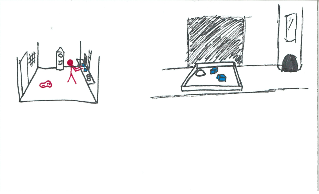
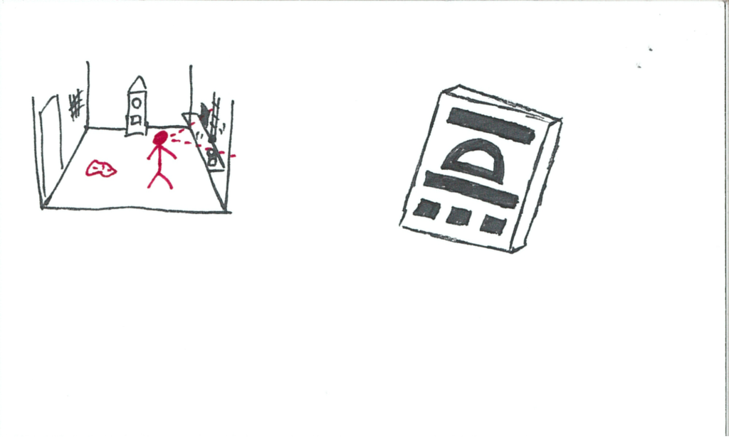
Left side of the card is usually going to be a stage-view of the user (red) in their environment.  Right side will often be a frameless point-of-view perspective sketch in the event that there’s something the user needs to see/do to further the story.  Other things worth noting are that interaction queues are drawn in red, often with dotted red lines denoting a field of view.  This could resemble an expectation of where the user will look, give reference to a perspective sketch, or be a view-triggered event.  There’s gonna be exceptions to these rules, but overall, understanding this format should allow the story to be communicable.

And so, Somniat begins:

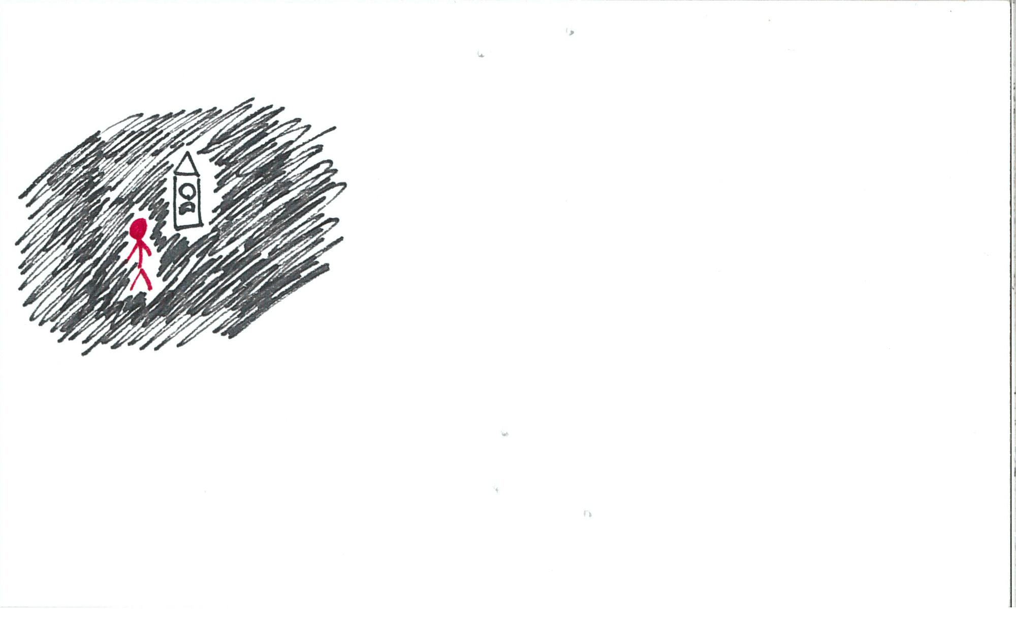
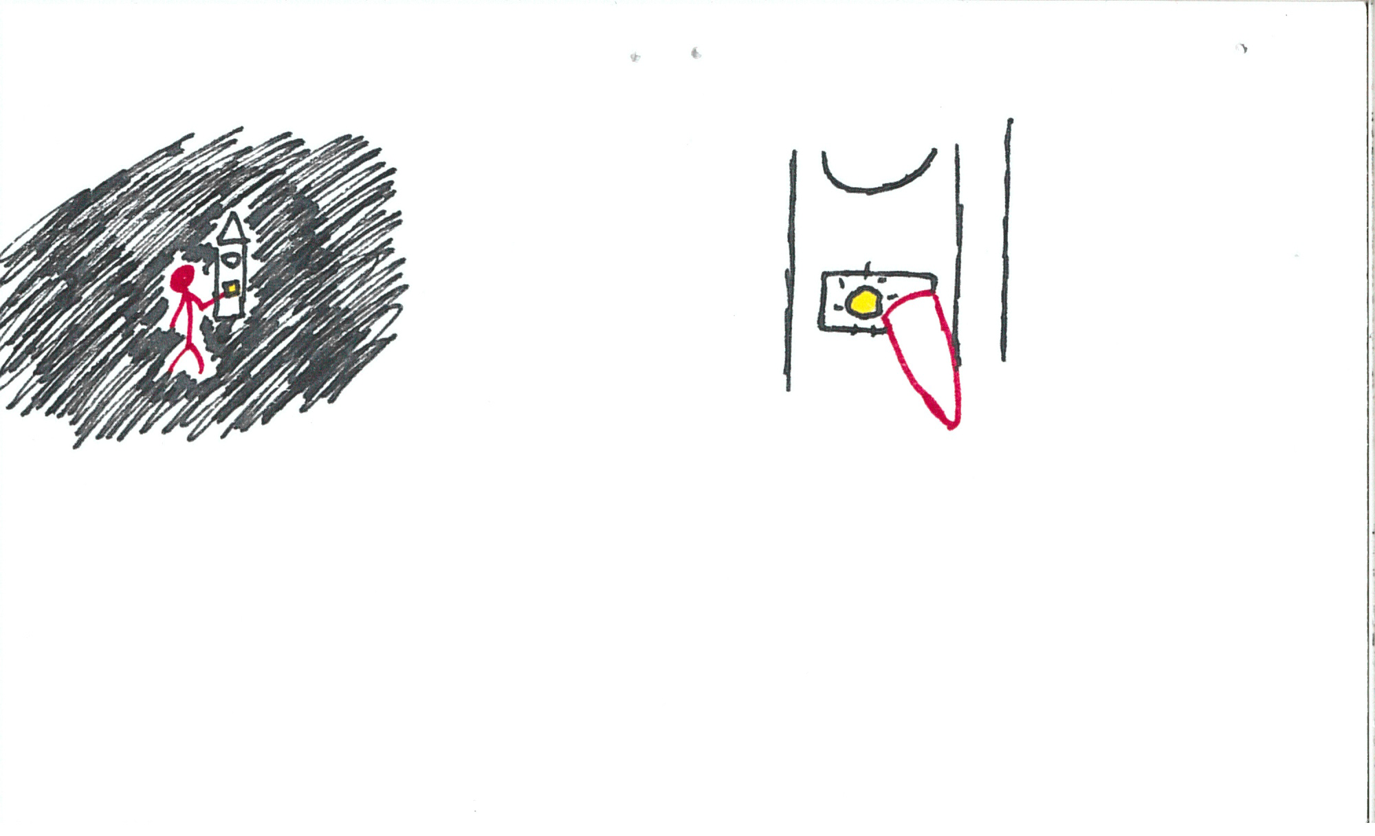
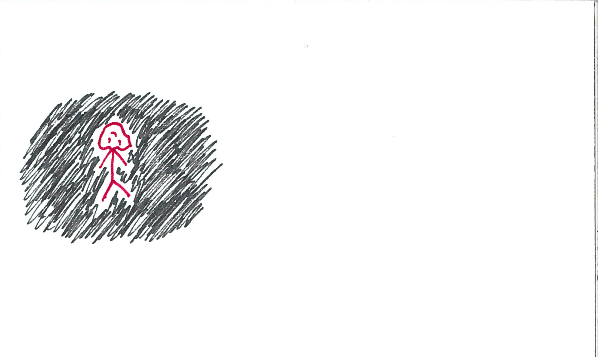
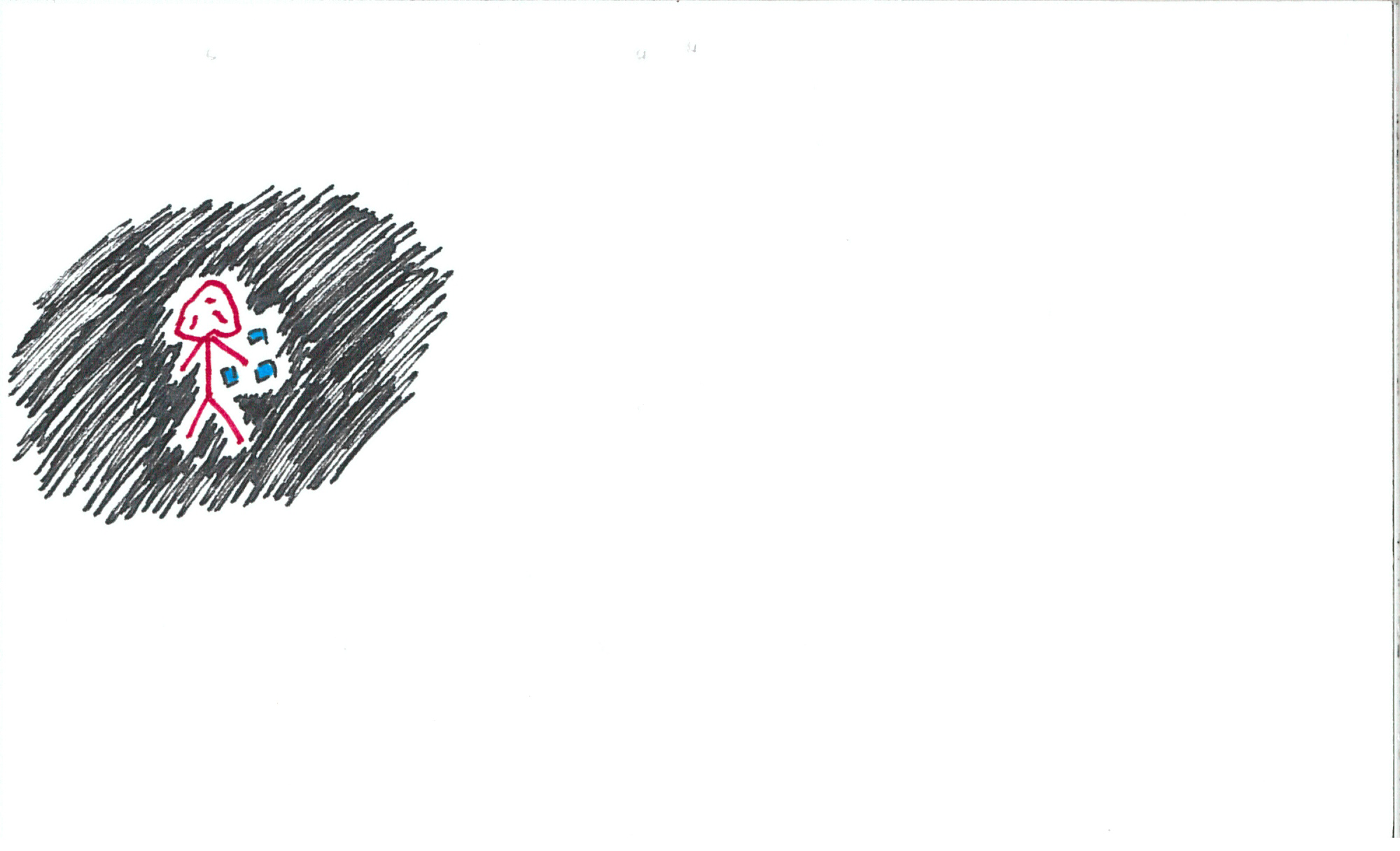
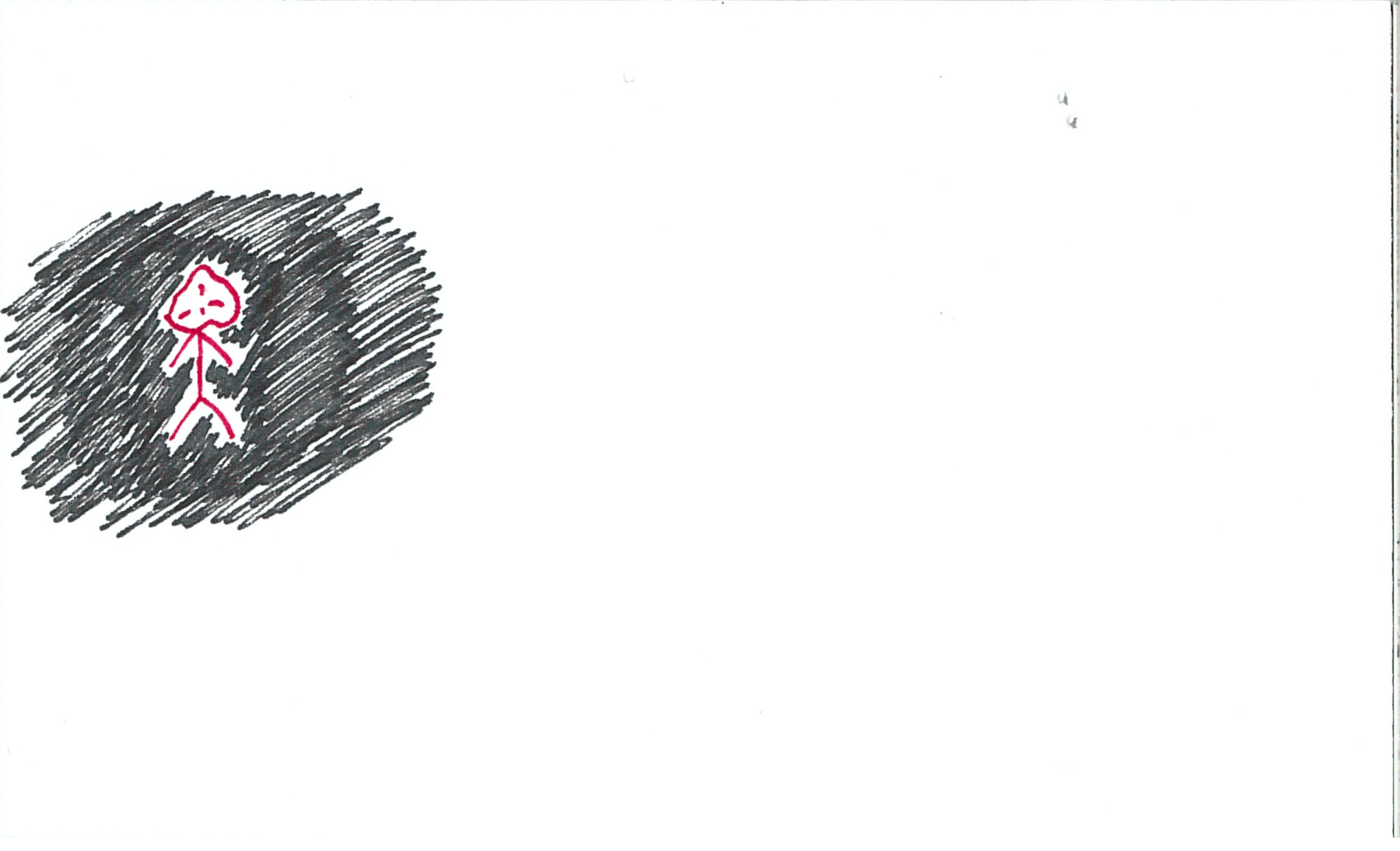
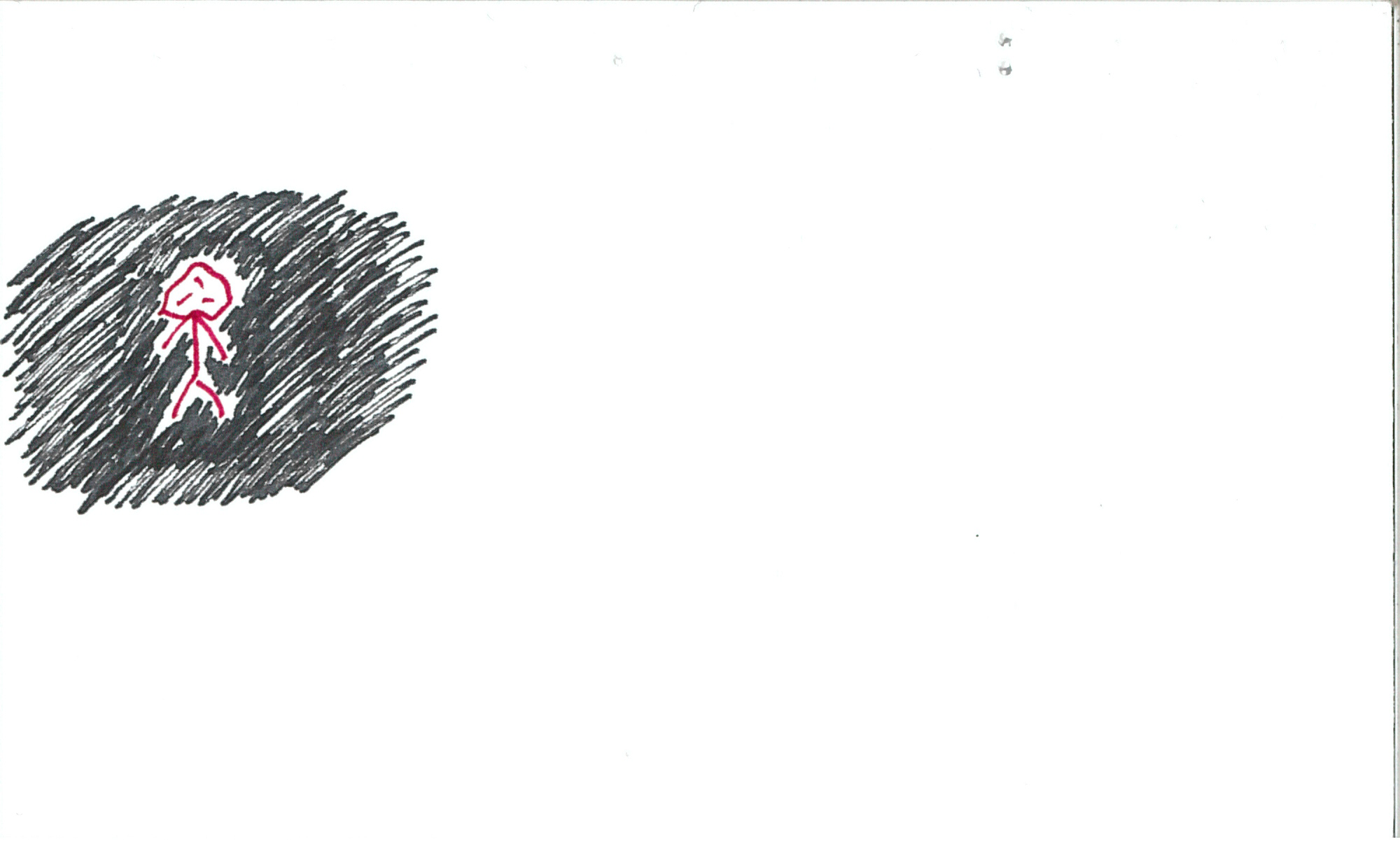
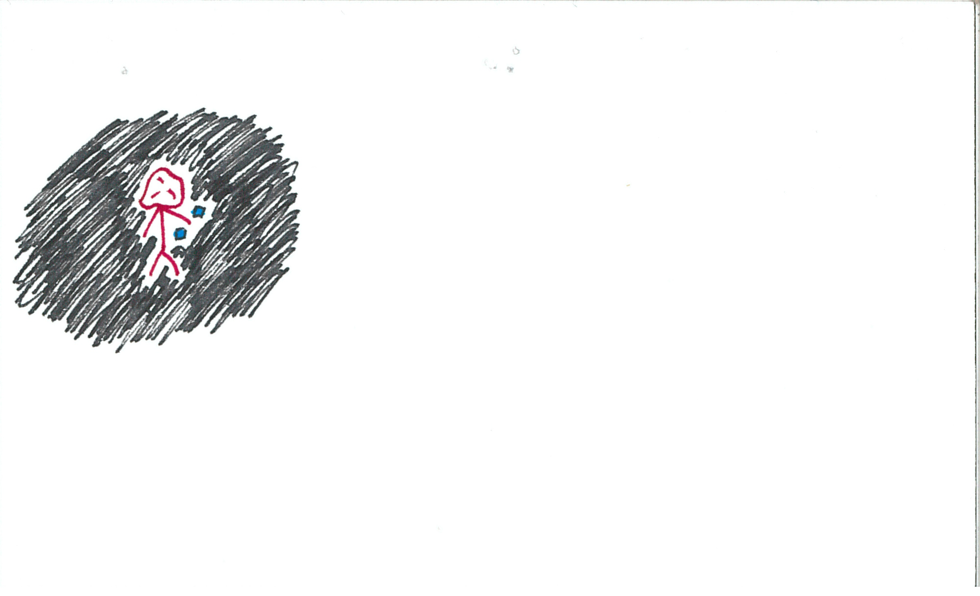
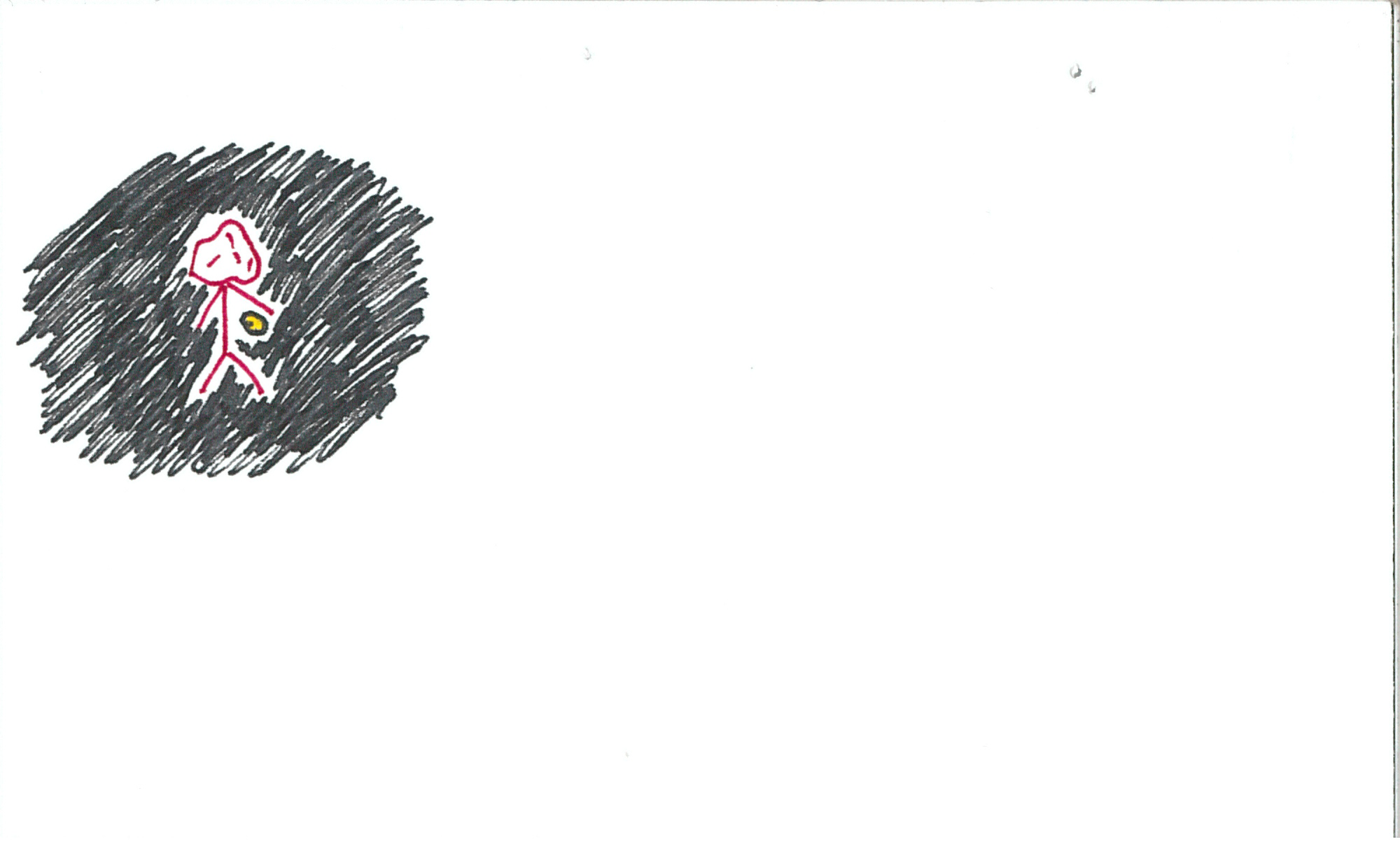
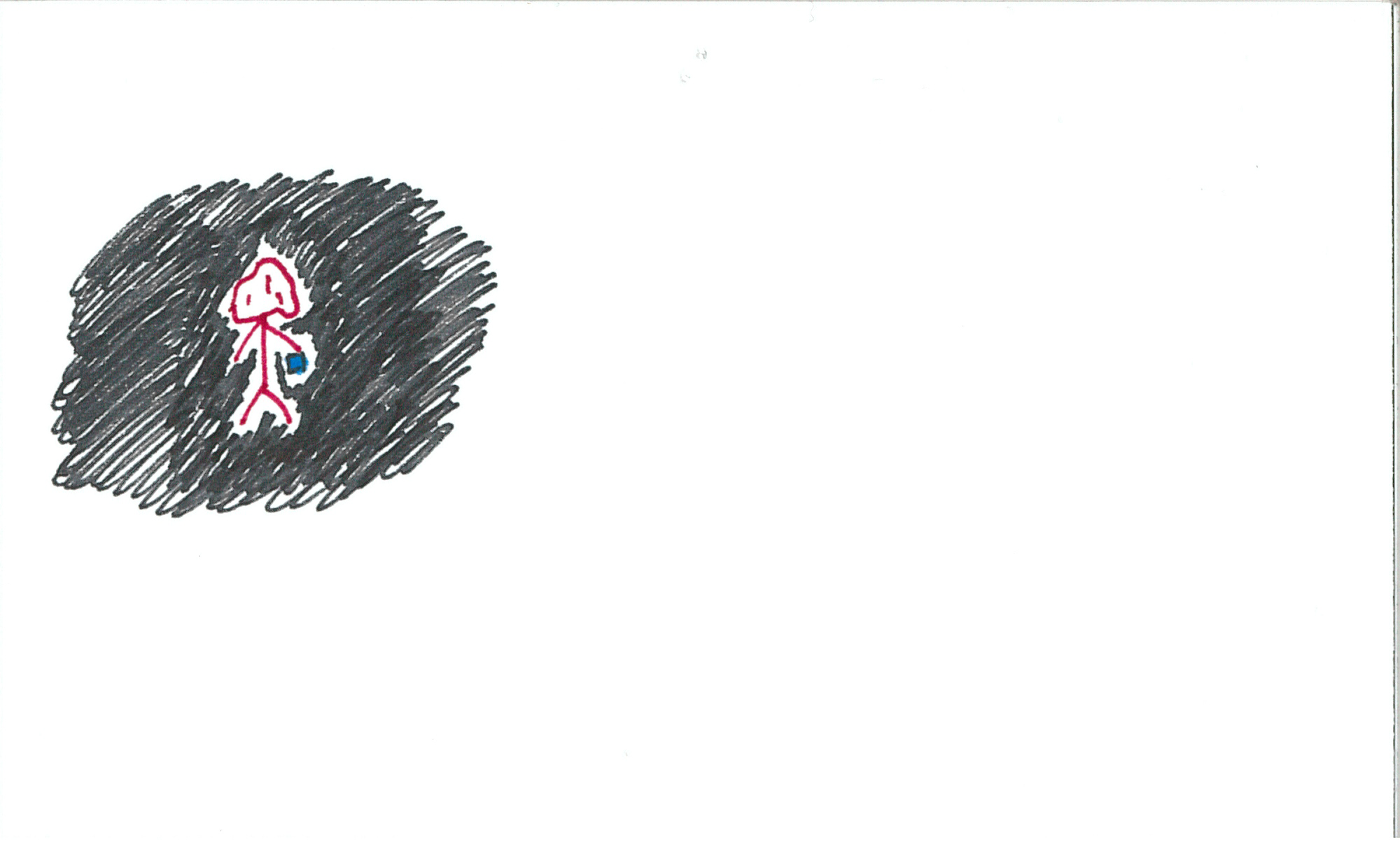
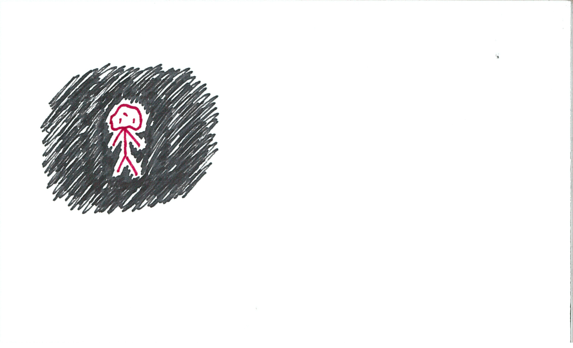
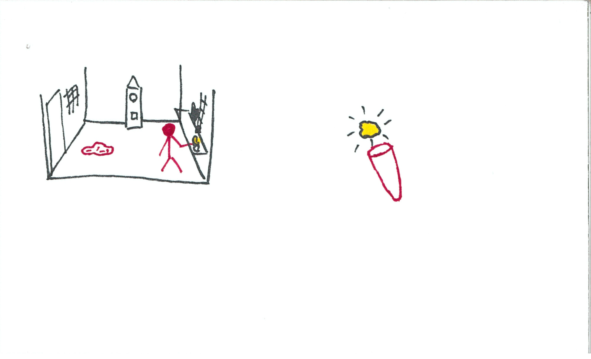
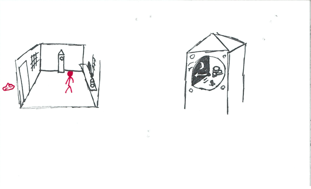
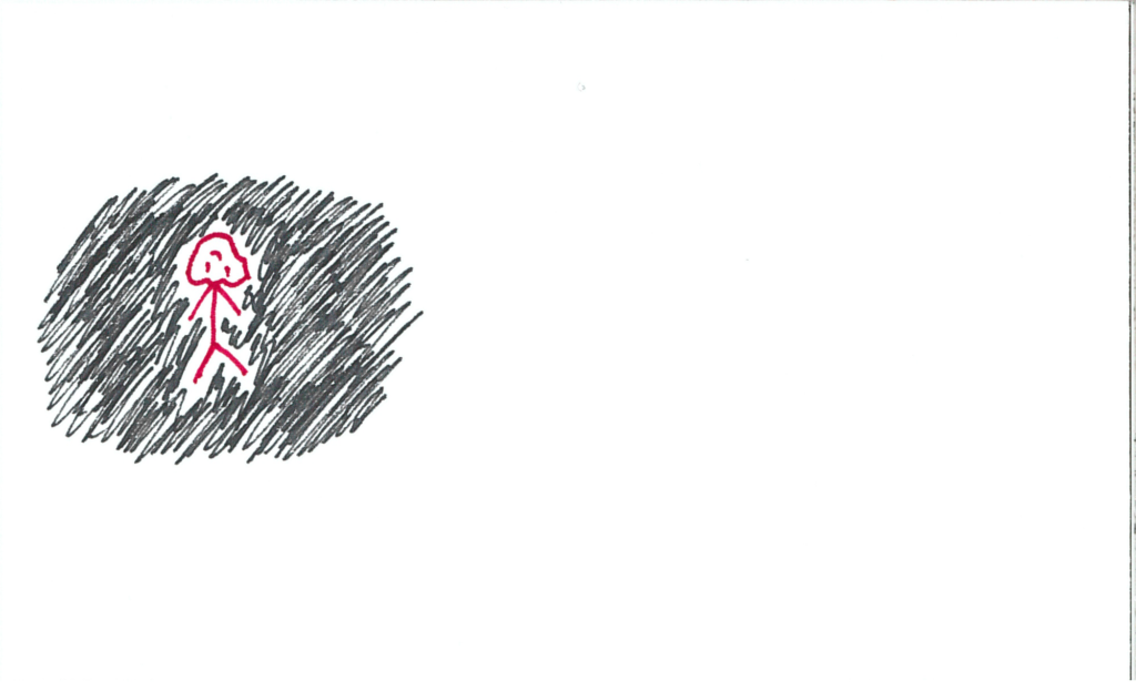
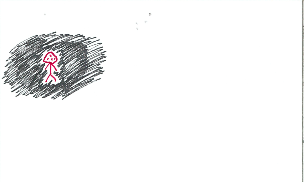
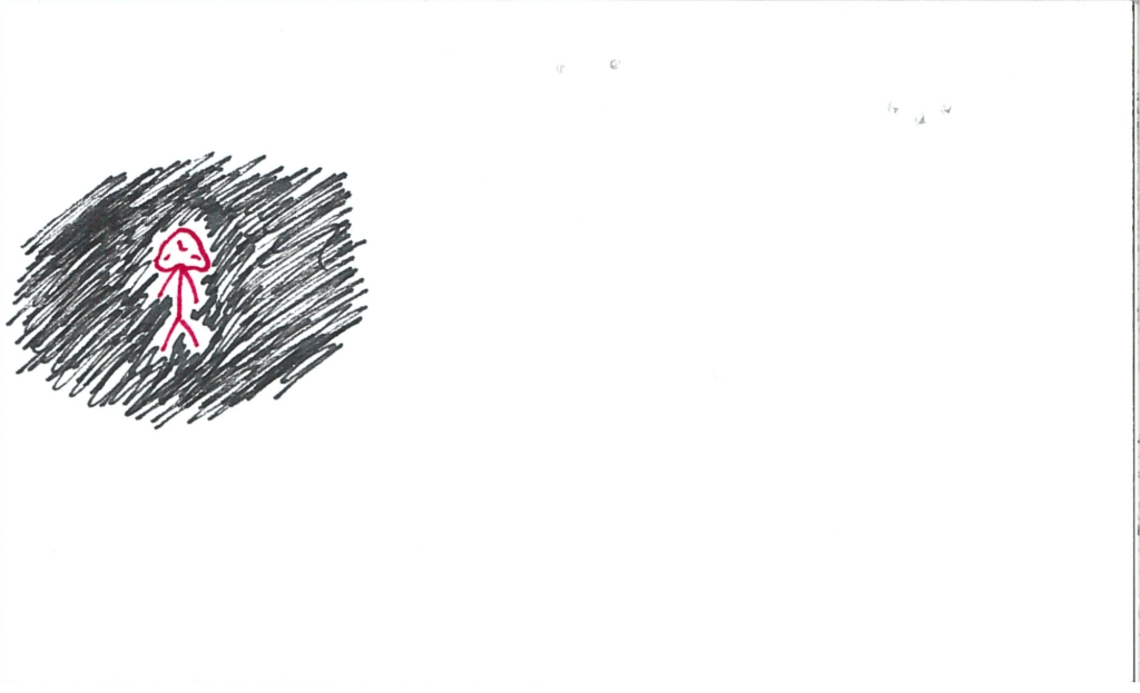
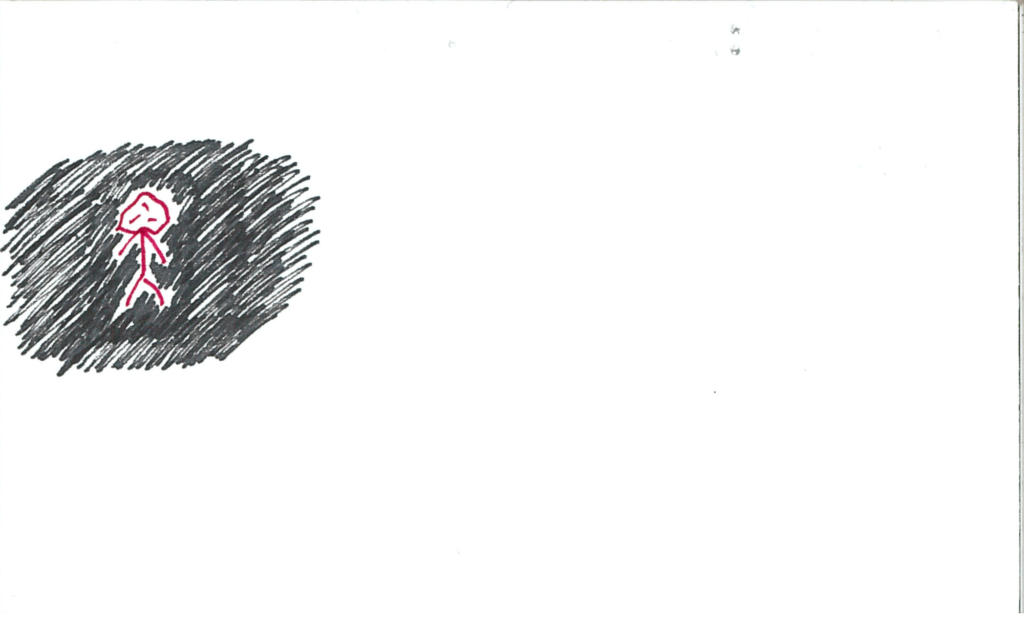
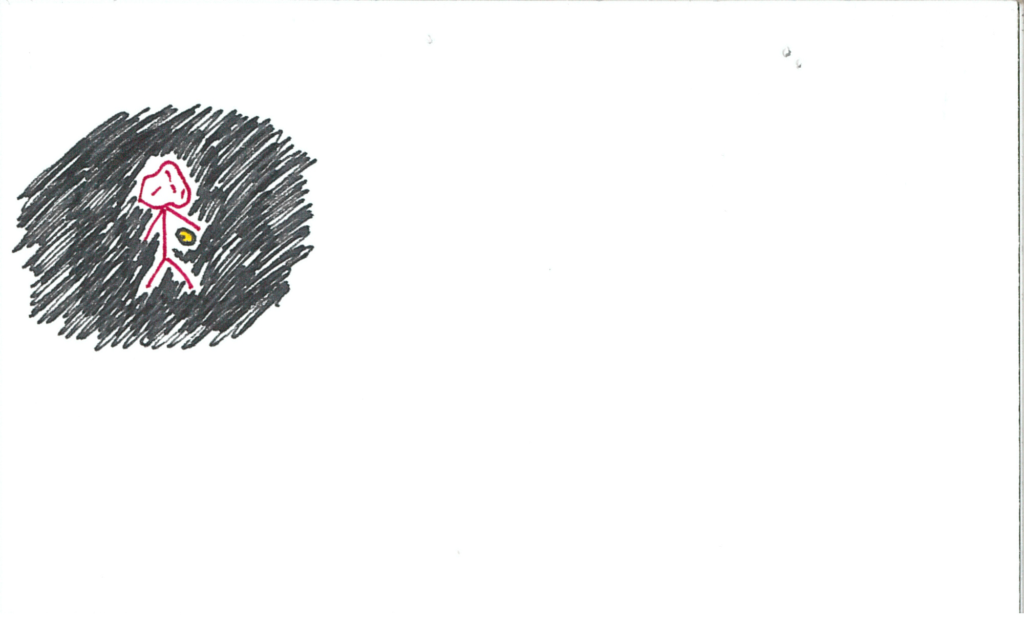
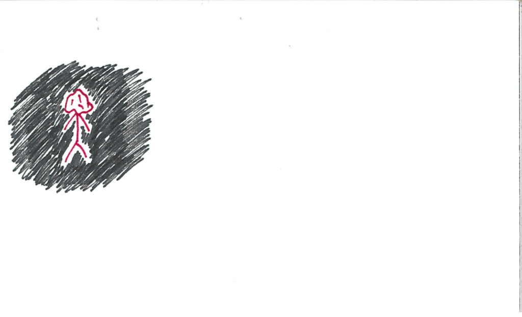
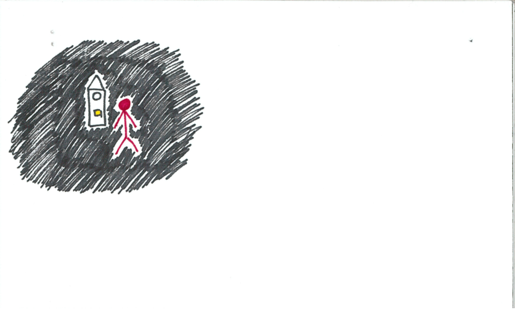
The user starts the experience in a dark void.  This is the “menu screen,” if you will.  Front and centre is a grandfather clock.

somniat-storyboard-panel-1

Upon looking at your hands/controllers, you have a glowing yellow orb in one of them.  The clock has a slot with a dim yellow light in it.

somniat-storyboard-panel-2

The user inserts the orb into the slot.  Music begins to play and the clock slowly lights up.

somniat-storyboard-panel-3

Introductory credits appear around the user in the void as the clock lights up.

somniat-storyboard-panel-4

somniat-storyboard-panel-5

somniat-storyboard-panel-6

somniat-storyboard-panel-7

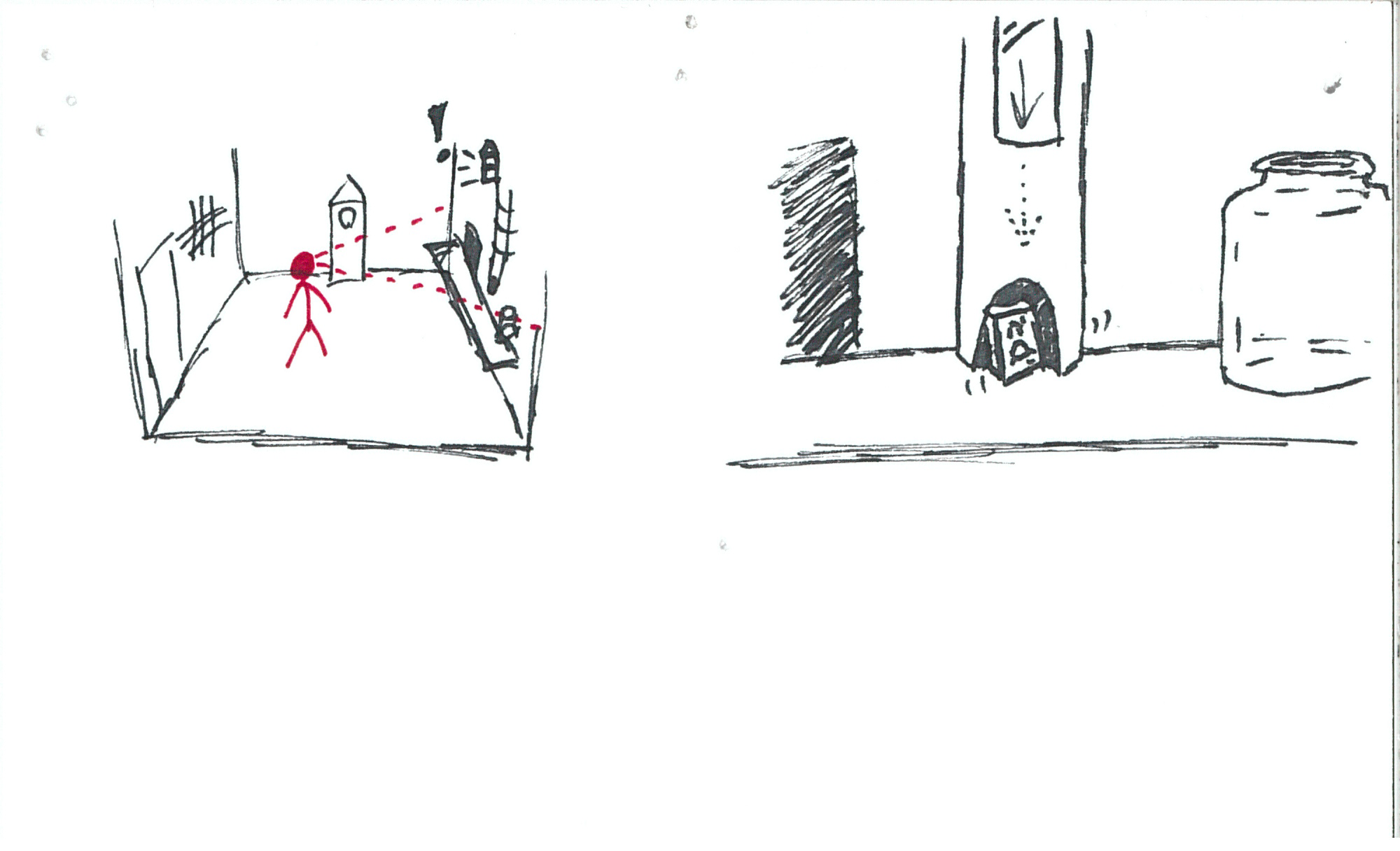
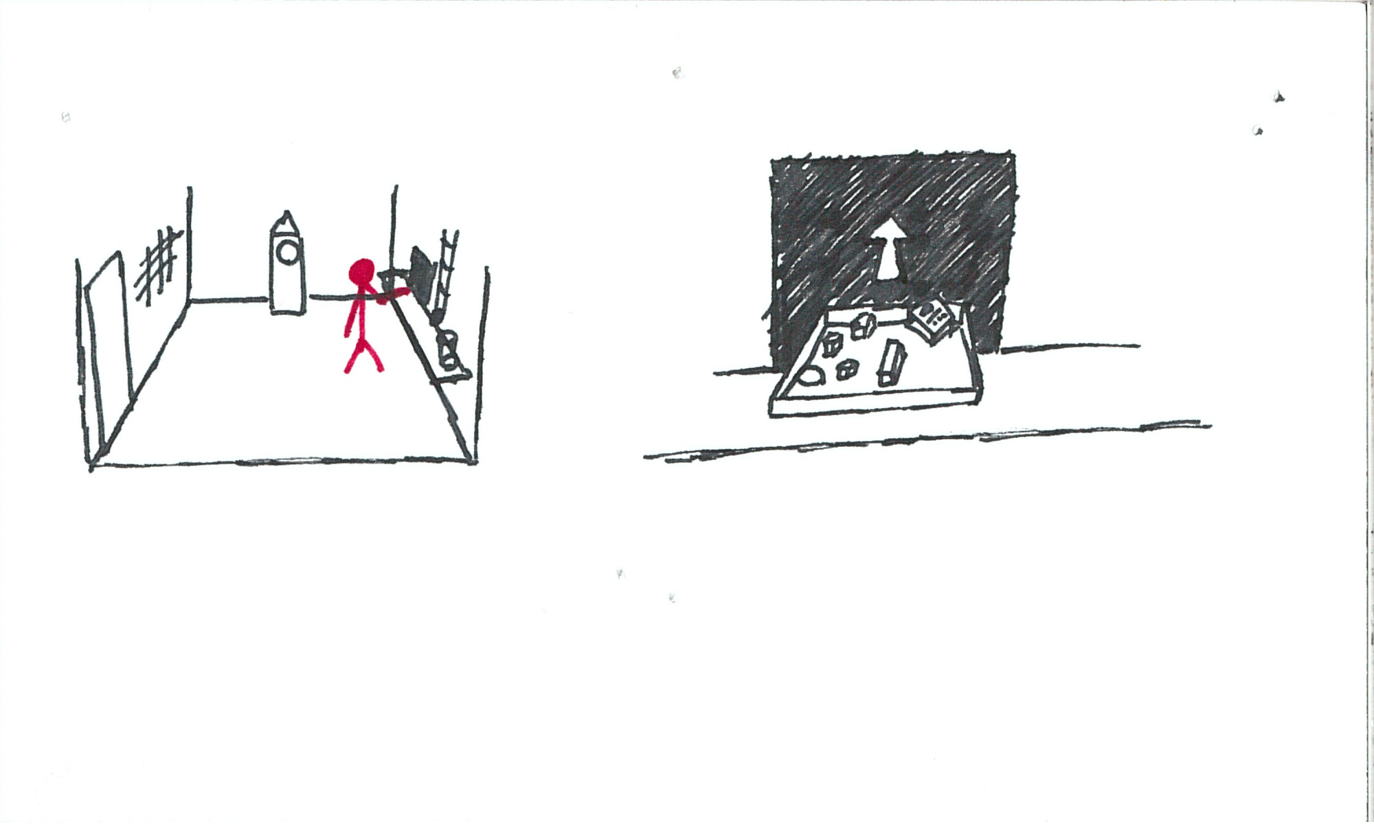
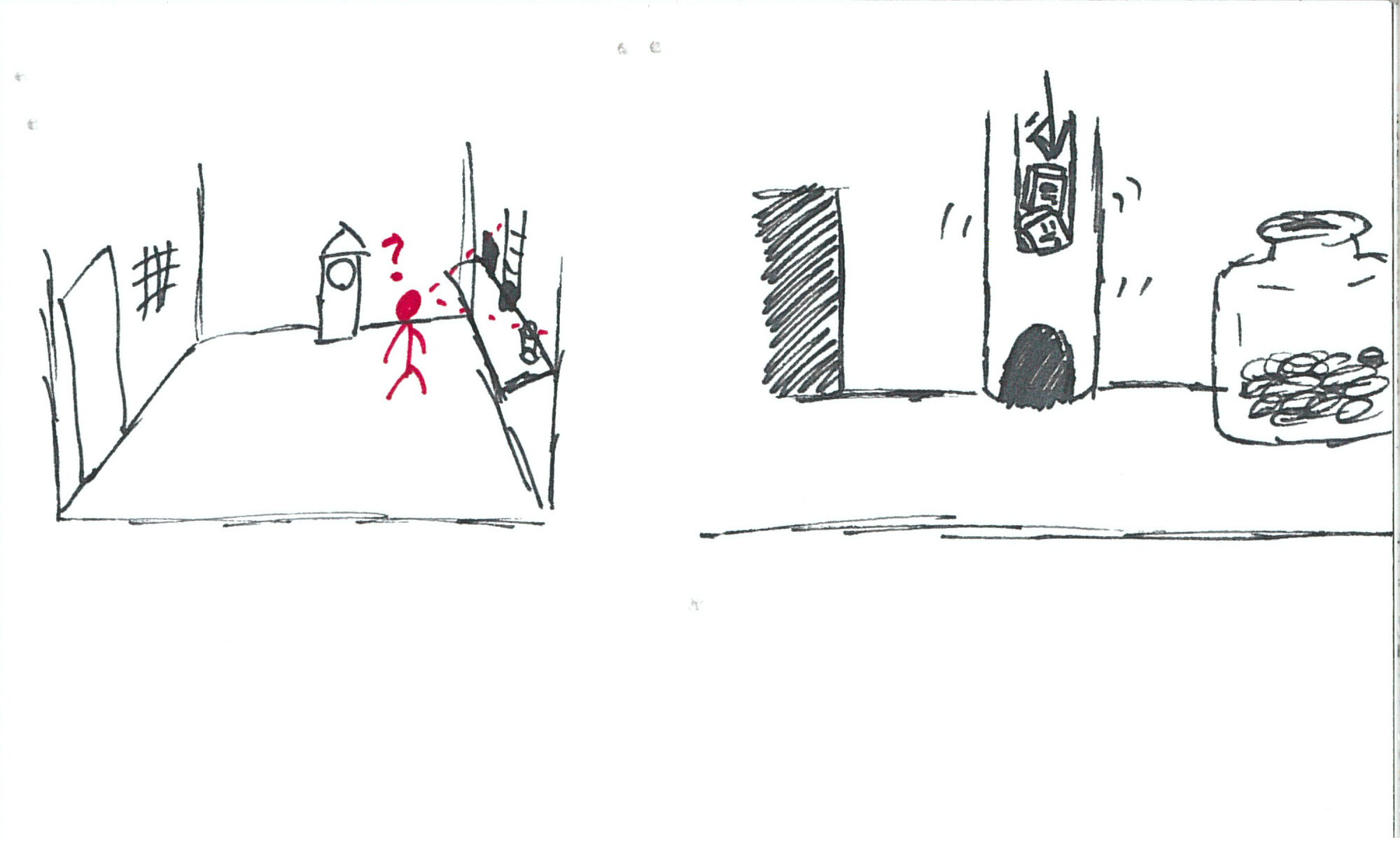
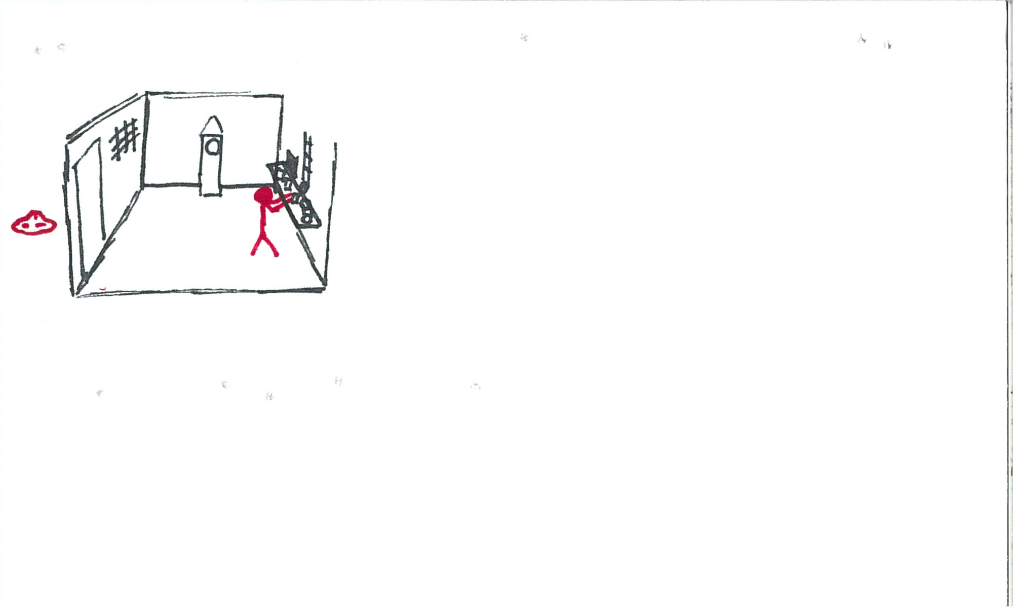
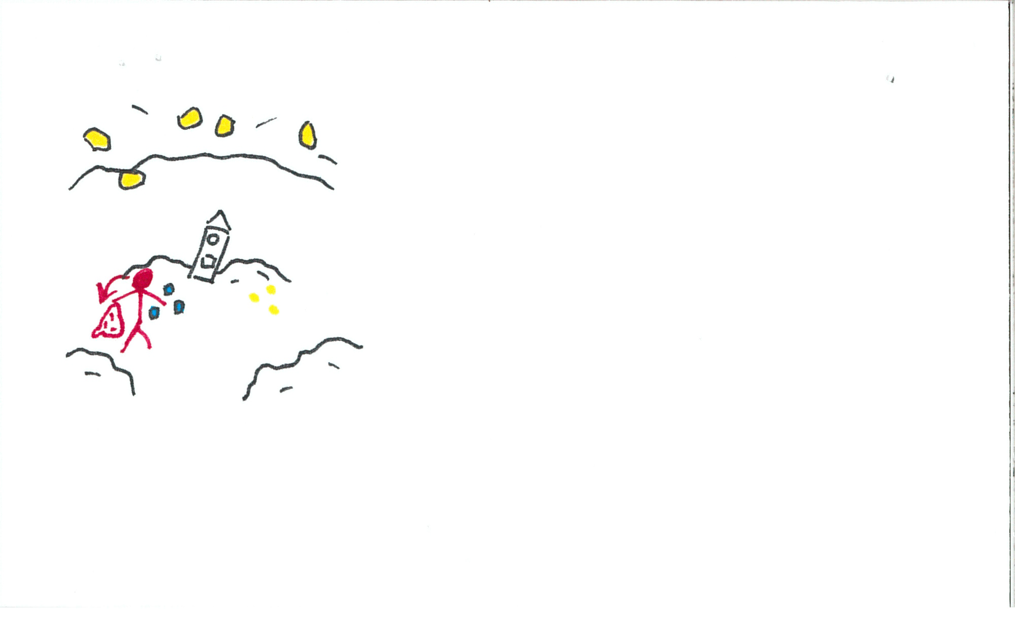
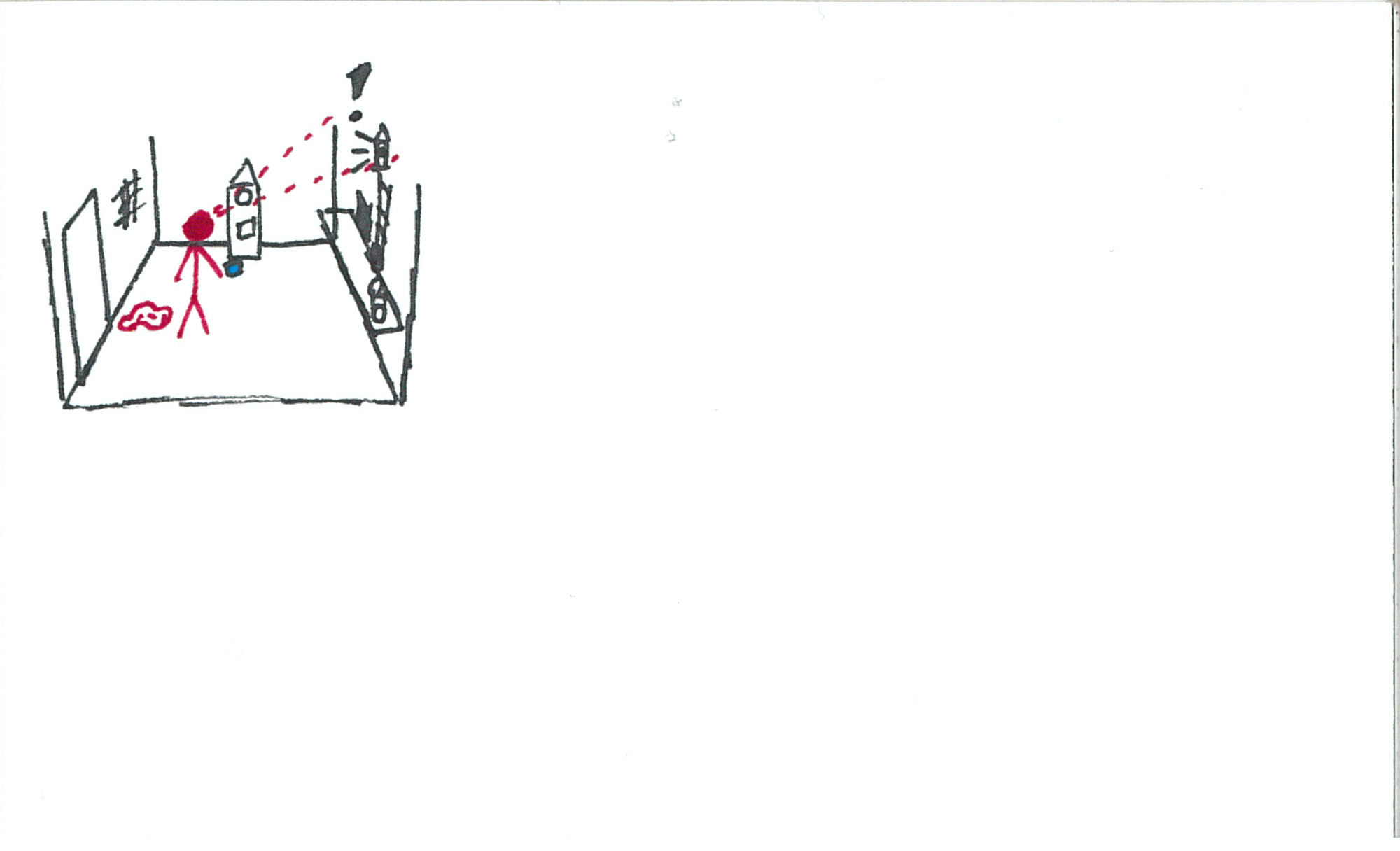
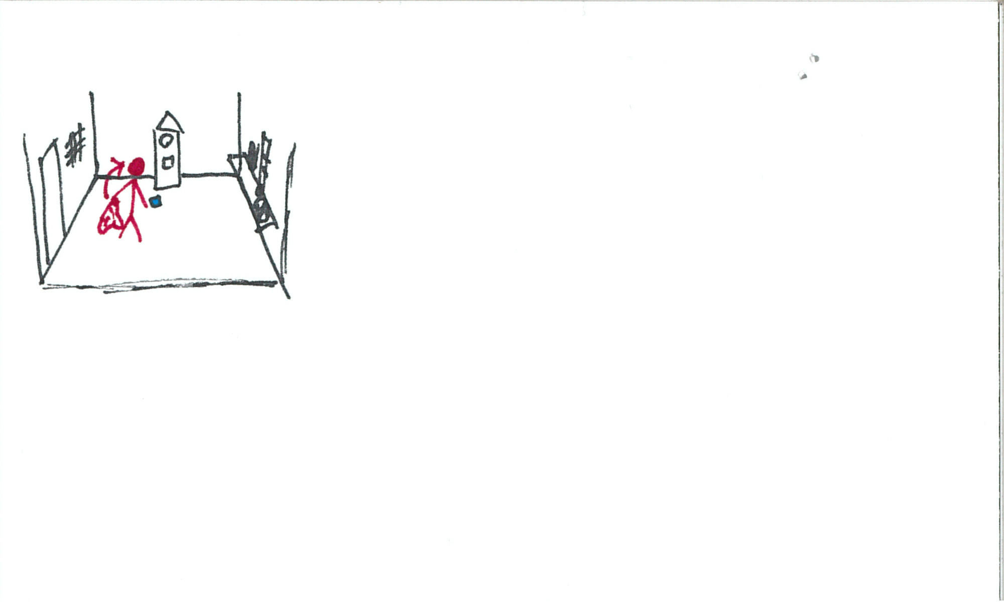
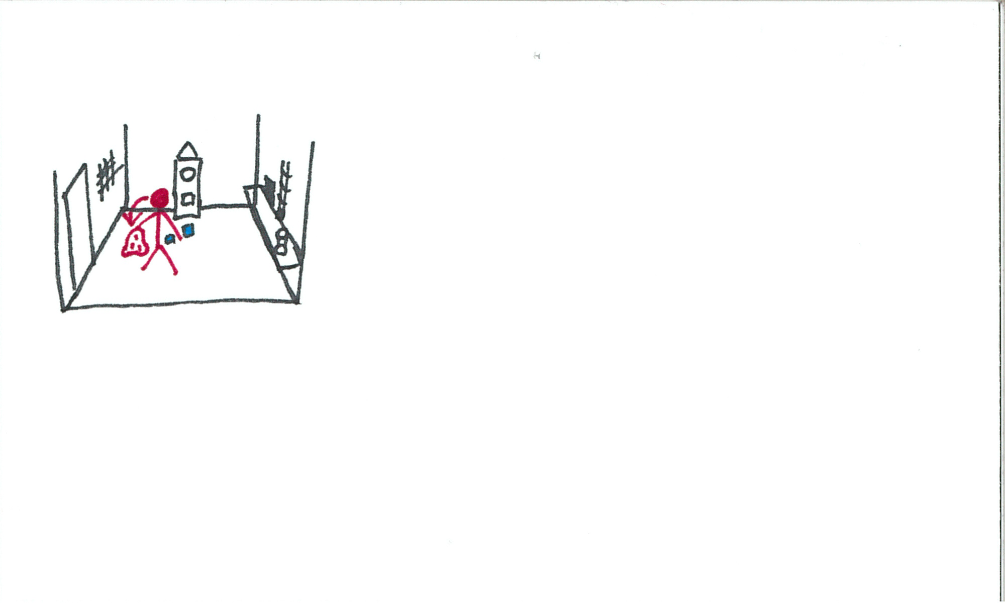
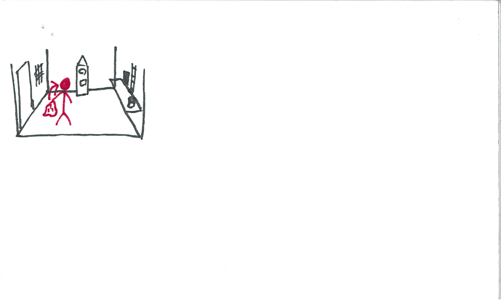
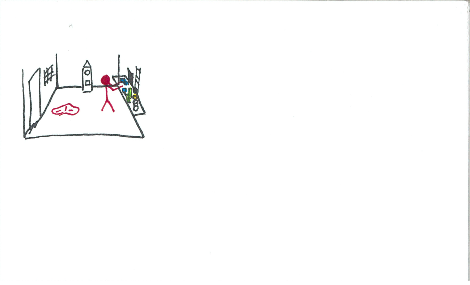
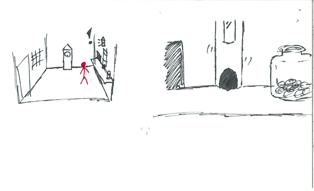
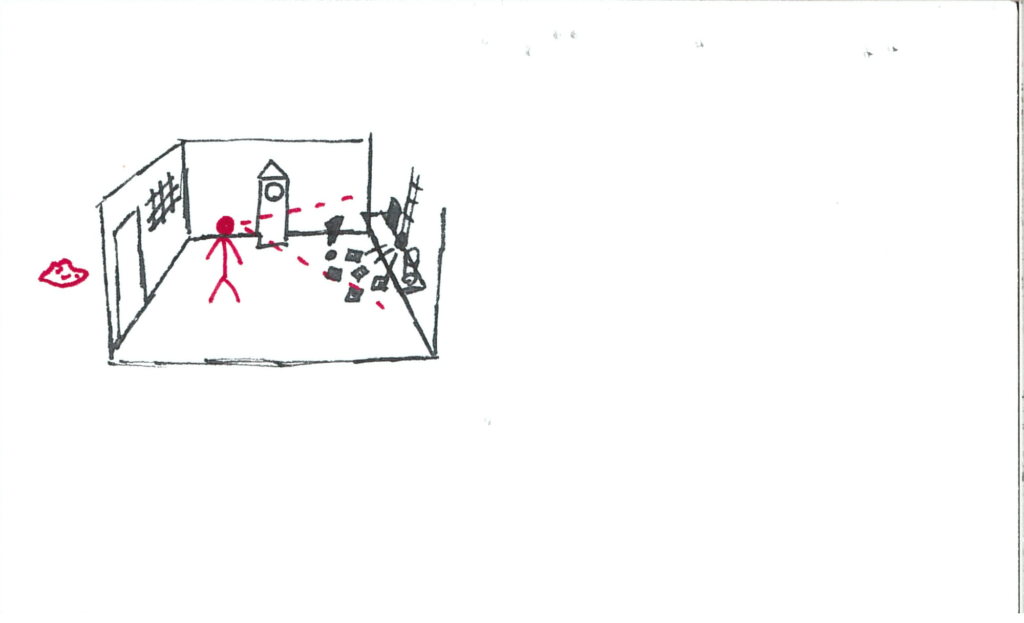
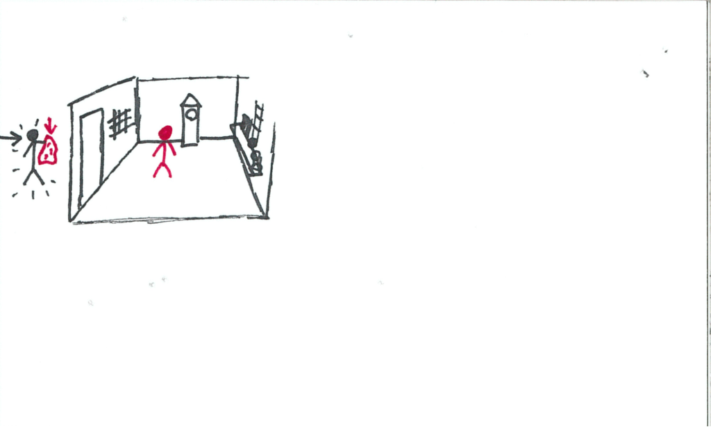
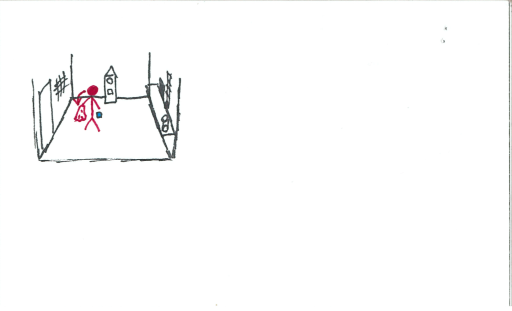
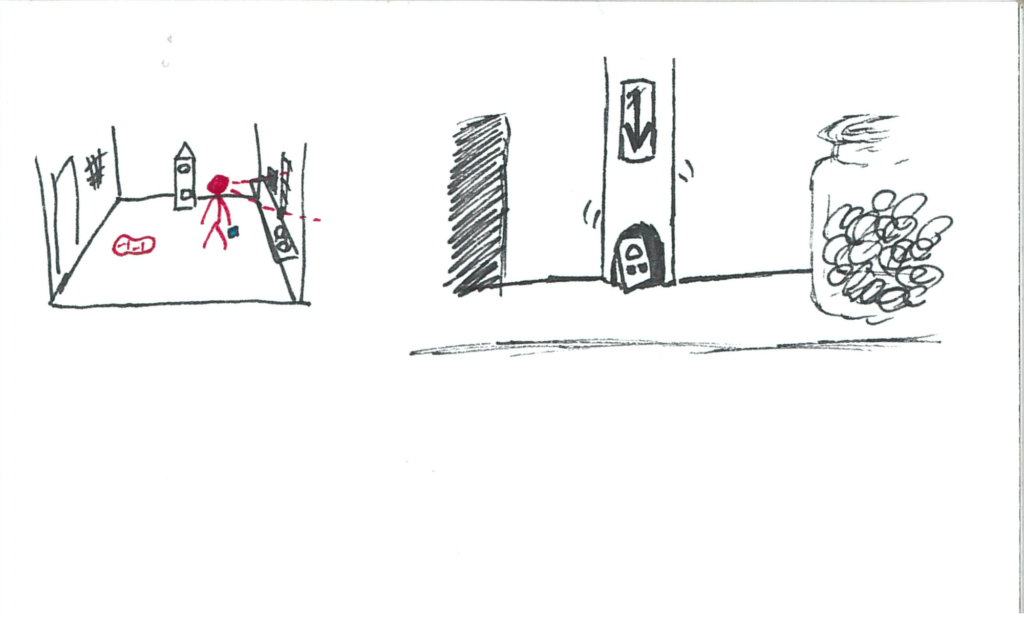
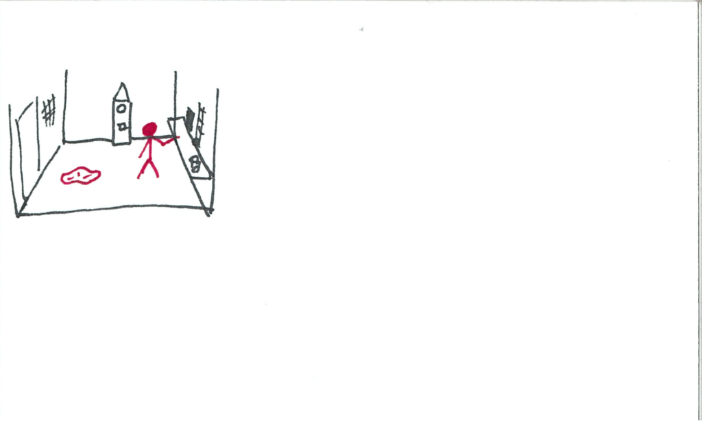
The music uncomfortably cuts and the user finds themselves in a small industrial room made of muted and cold colors.  The grandfather clock is still to the front, workstation to the right, and a door and barred-window to the left.

somniat-storyboard-panel-8

The clock chimes.  Its hand ticks from “nighttime” to “work”.

somniat-storyboard-panel-9

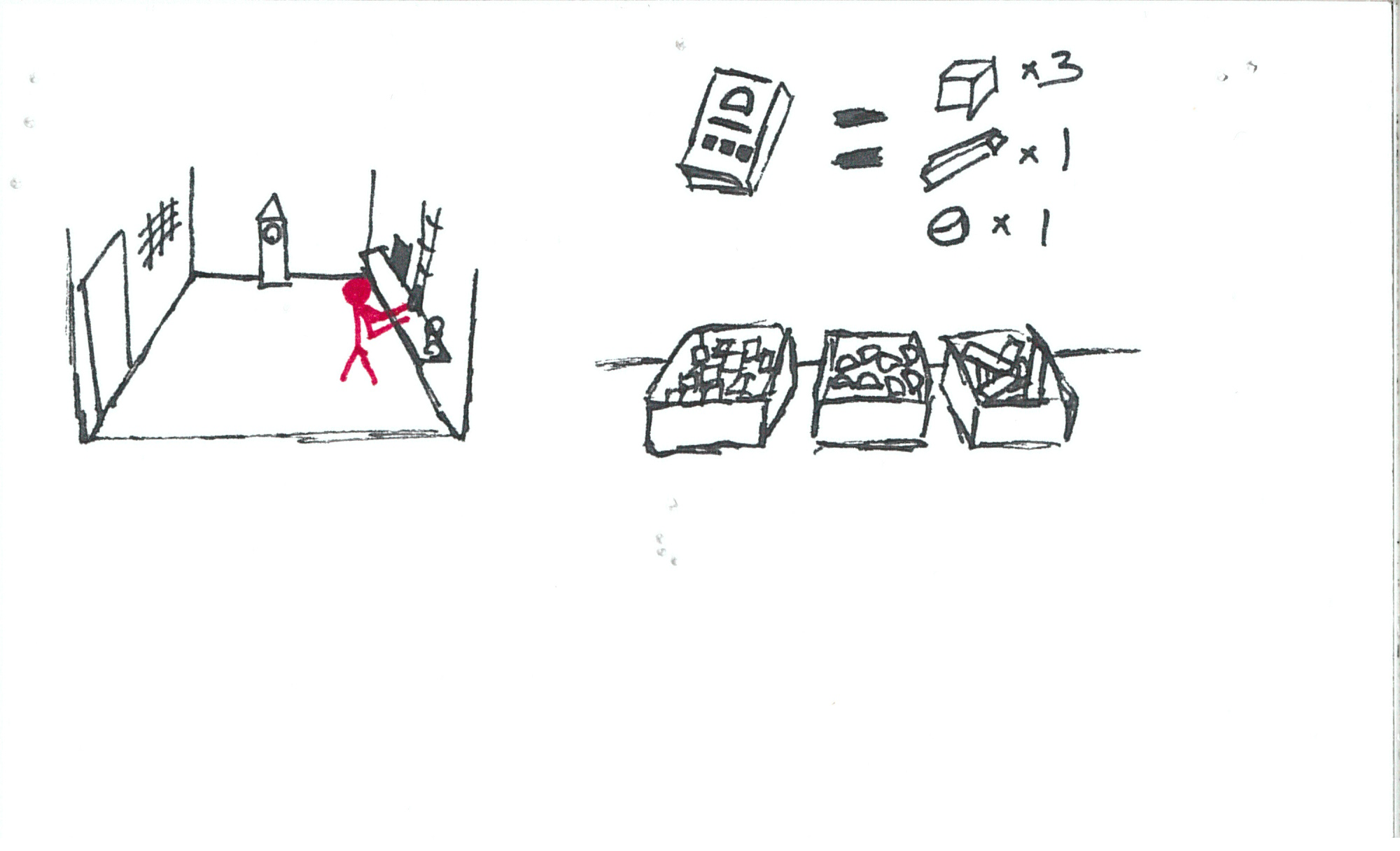
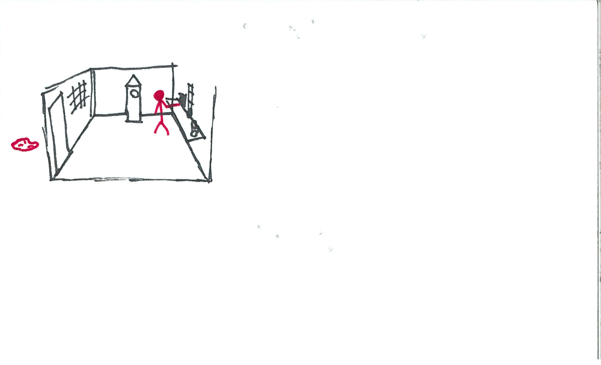
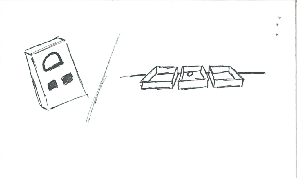
A whistle above the workstation sounds.  A wooden block/tag falls down the pipe.

somniat-storyboard-panel-10

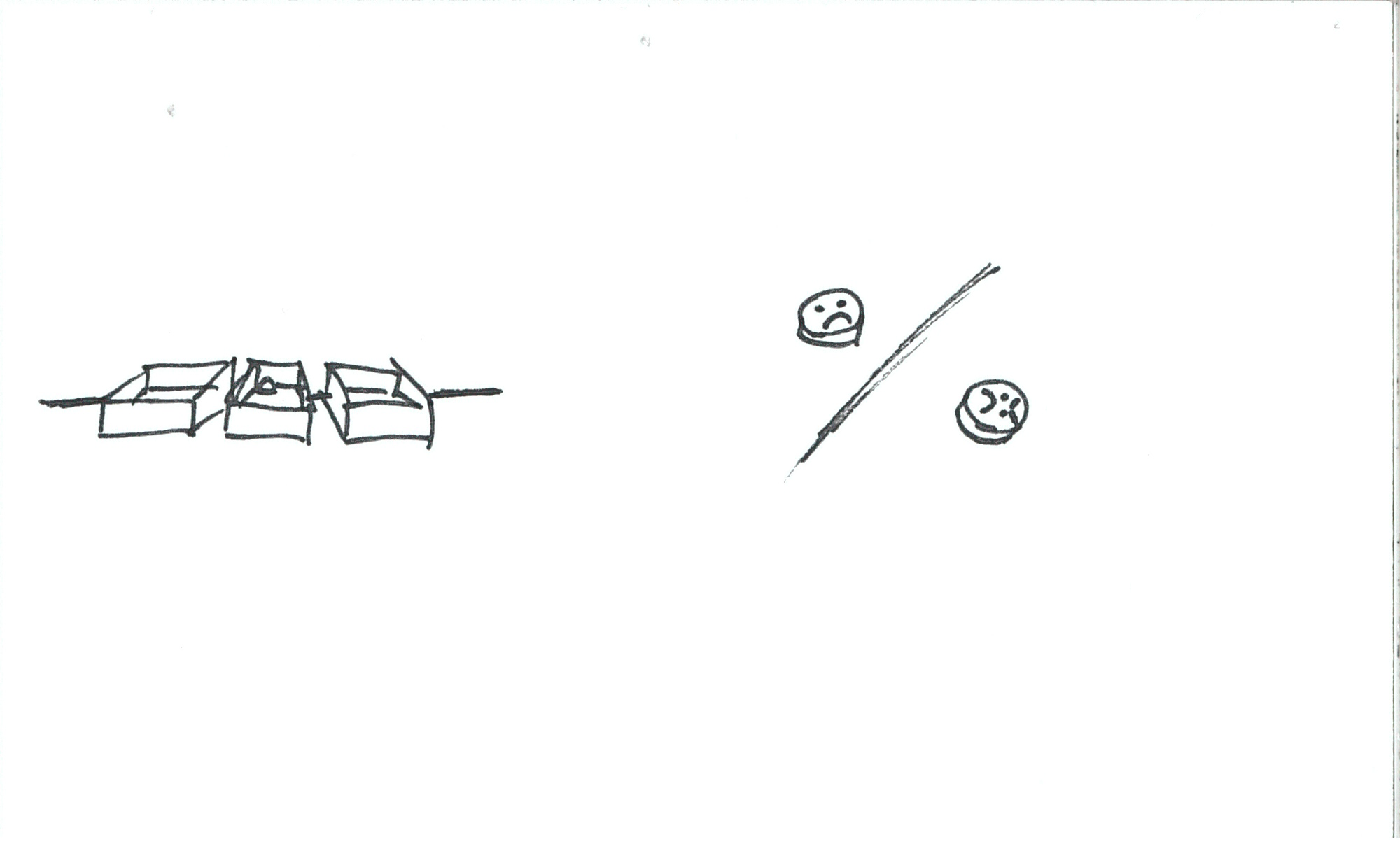
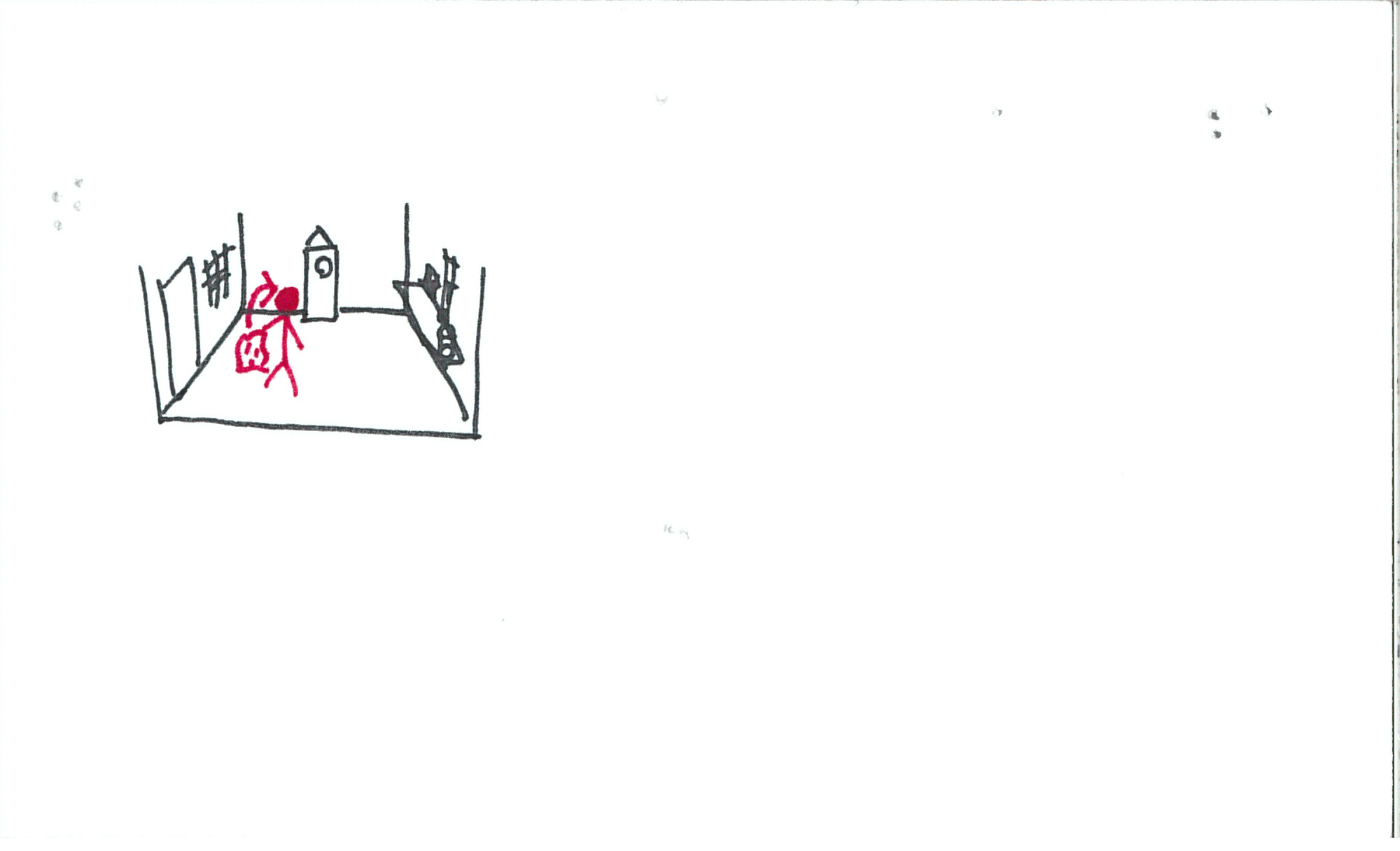
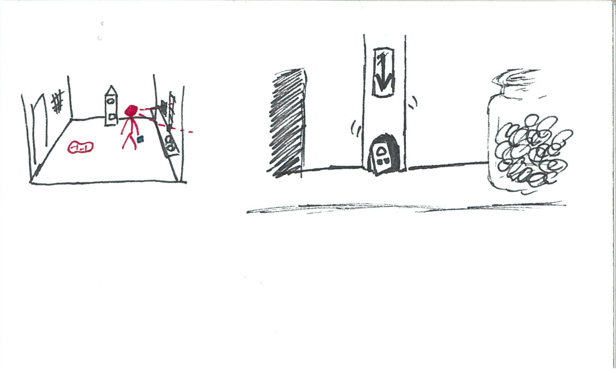
The tag has basic geometric shapes on it (square, semicircle, or line).  Below the main workstation shelf is a second shelf with 3 bins on it.  Inside these bins are basic geometric solids (cubes, hemispheres, rods).

somniat-storyboard-panel-11

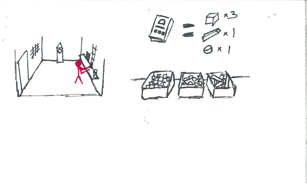
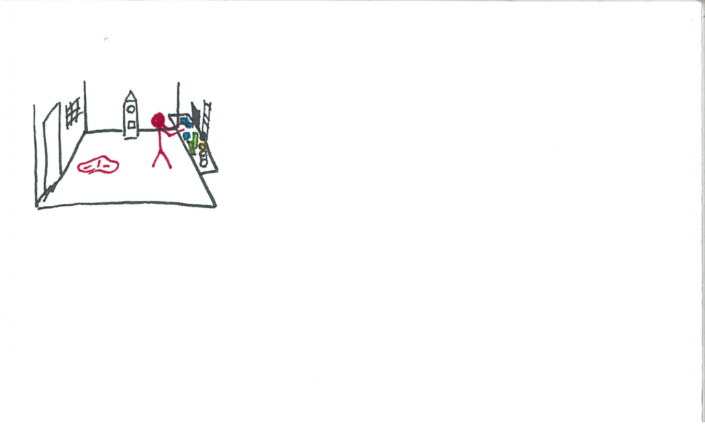
The user places the geometric objects requested by the tag onto a tray that’s travelling on a conveyor.  It leaves the room.

somniat-storyboard-panel-12

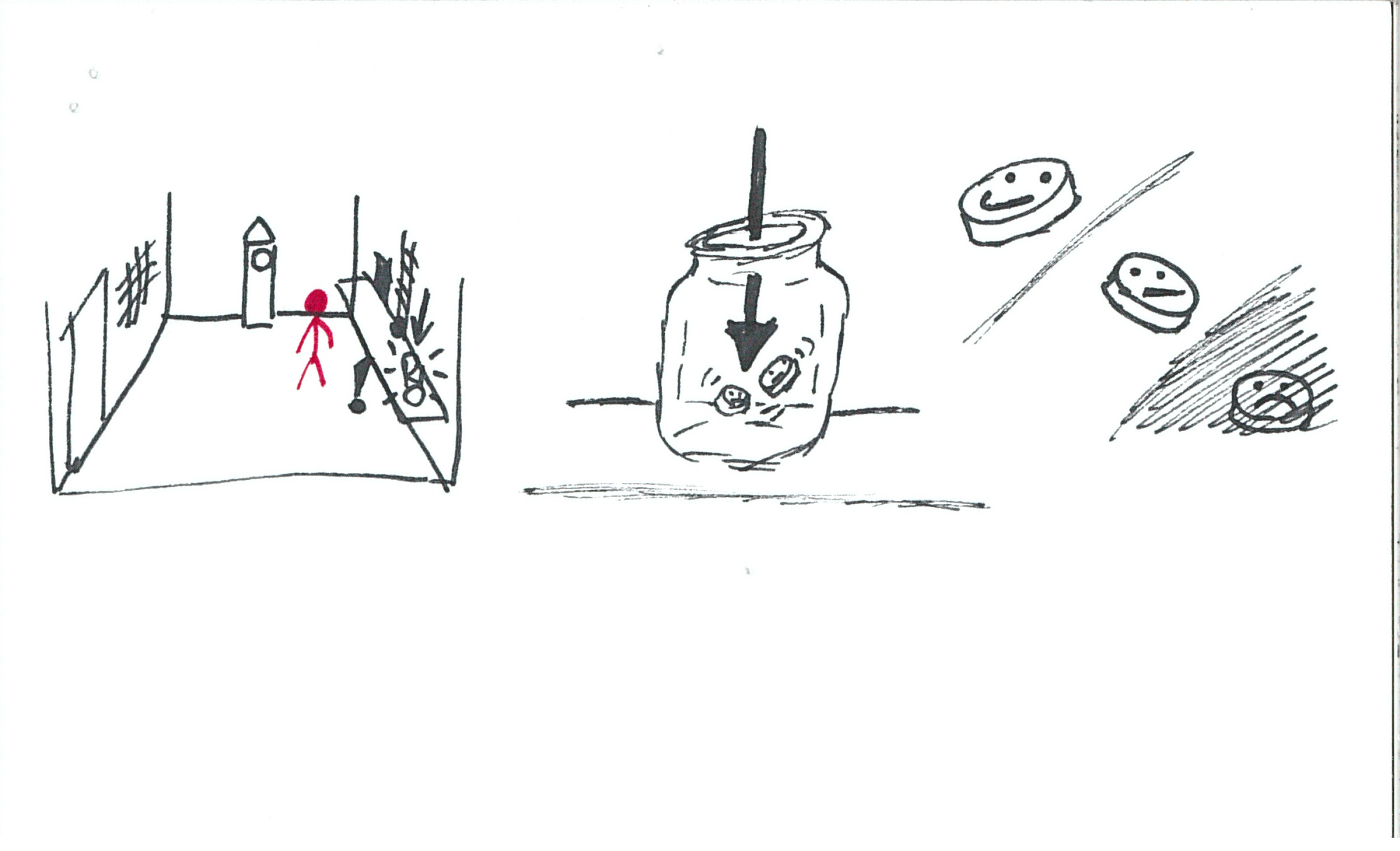
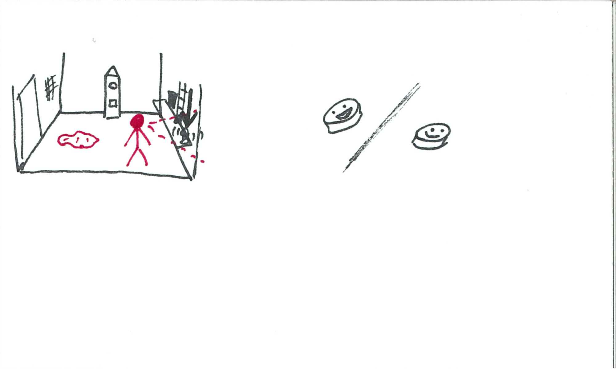
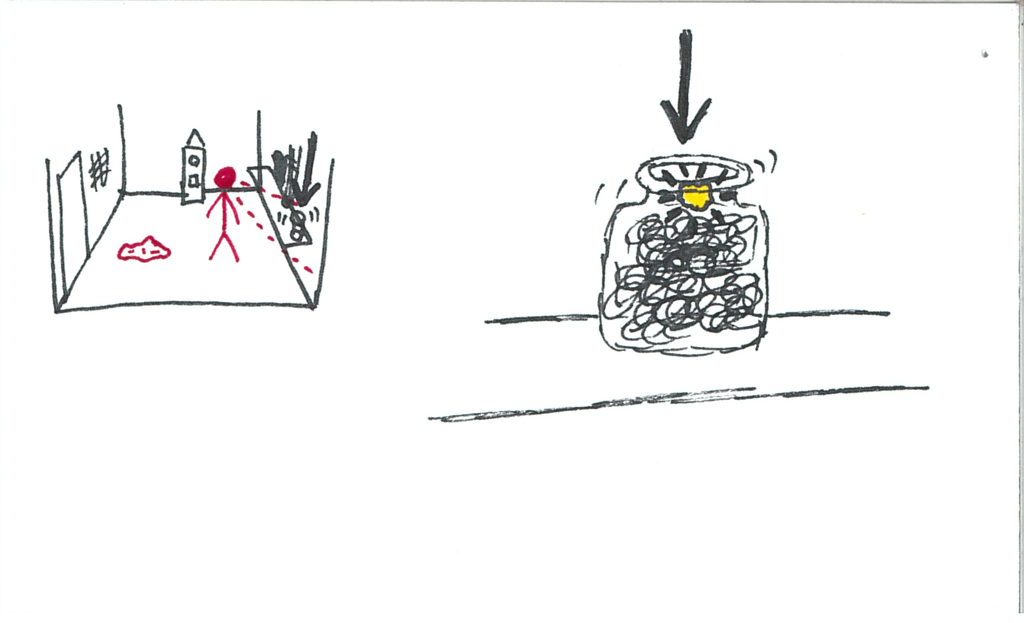
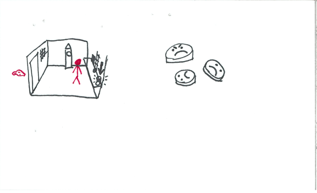
Money falls down into a jar on the edge of the workstation shelf.  The coins have emotions drawn on them.

somniat-storyboard-panel-13

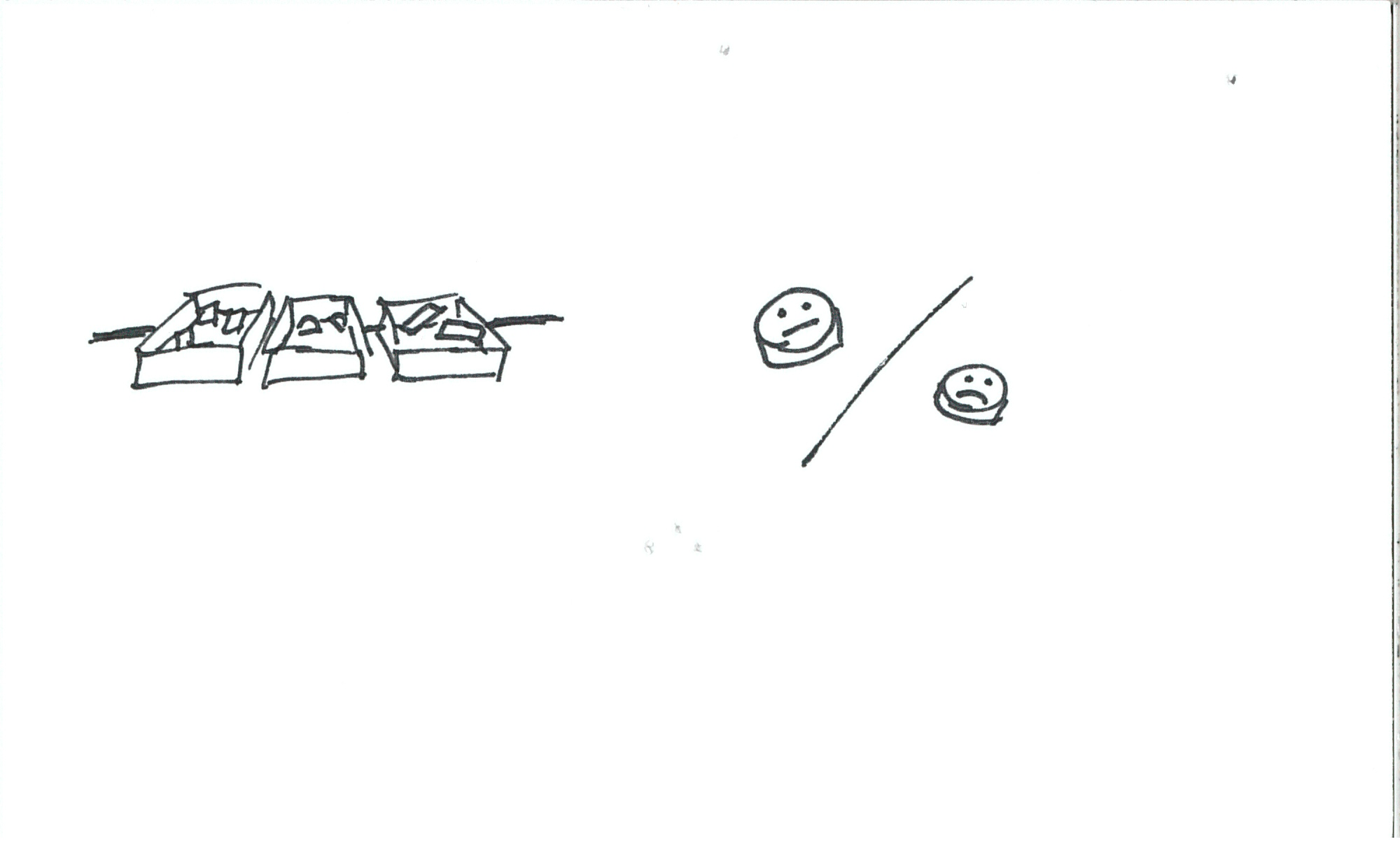
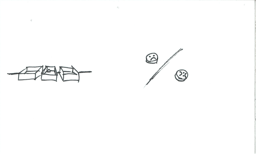
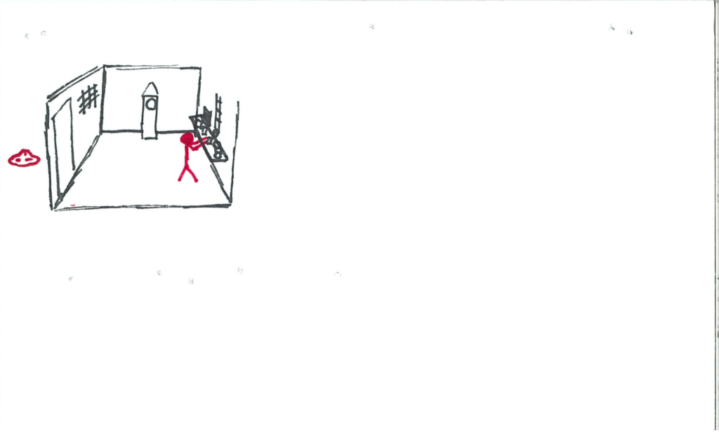
The user continues fulfilling orders, but supplies start running low.  Customers are giving less satisfactory emotions.

somniat-storyboard-panel-14

There’s nearly no resources left and the user is forced to send out incomplete orders.  Customers are very dissatisfied.

somniat-storyboard-panel-15

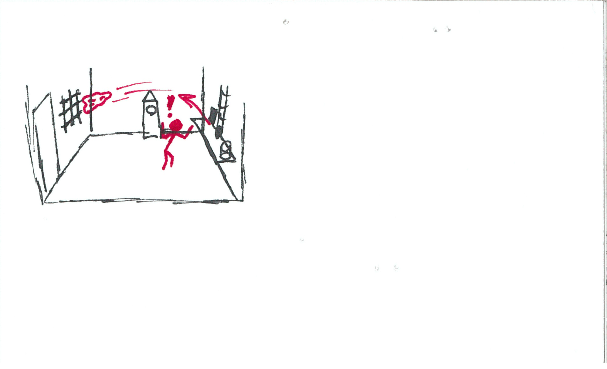
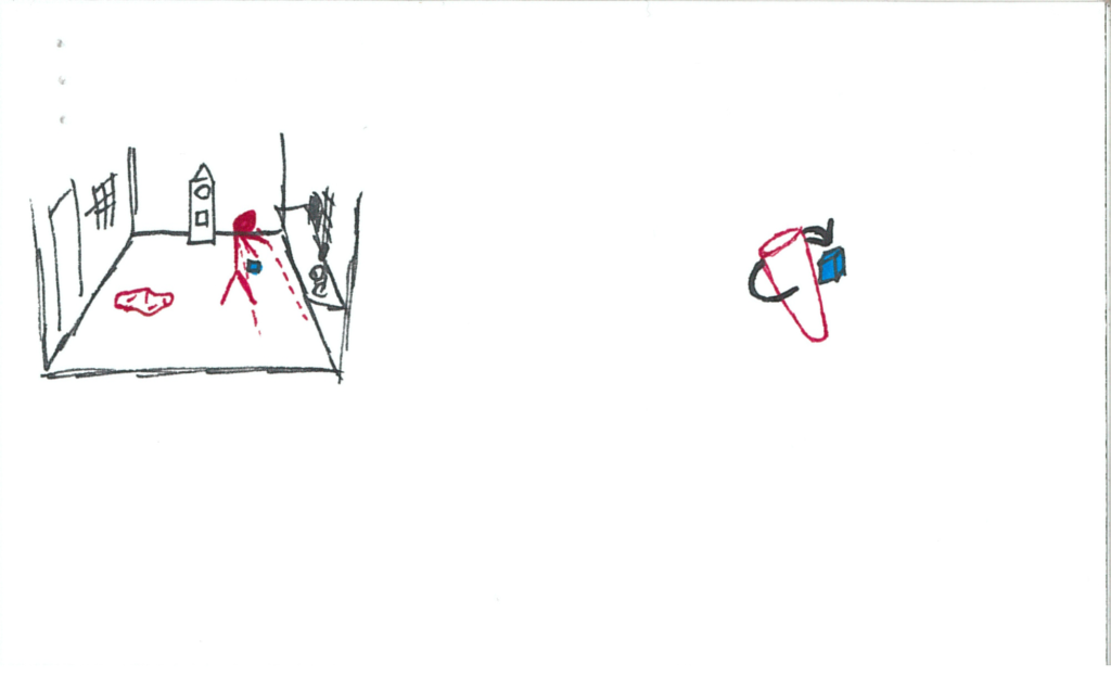
The whistle blows as usual, however no tag arrives.

somniat-storyboard-panel-16

More tags fall down the pipe but do not come out.

somniat-storyboard-panel-17

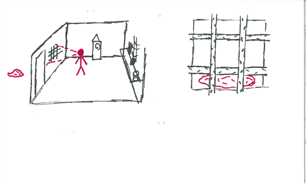
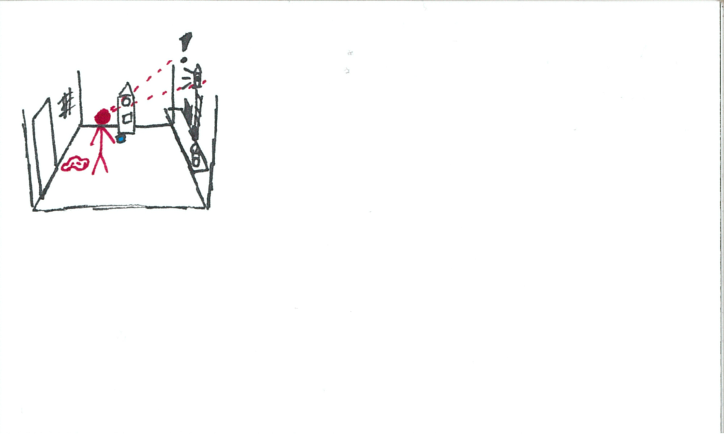
A vibrant red blanket shoots out of the pipe and is launched across the room!

somniat-storyboard-panel-18

It gets propelled through the grated window, out of the user’s reach.

somniat-storyboard-panel-19

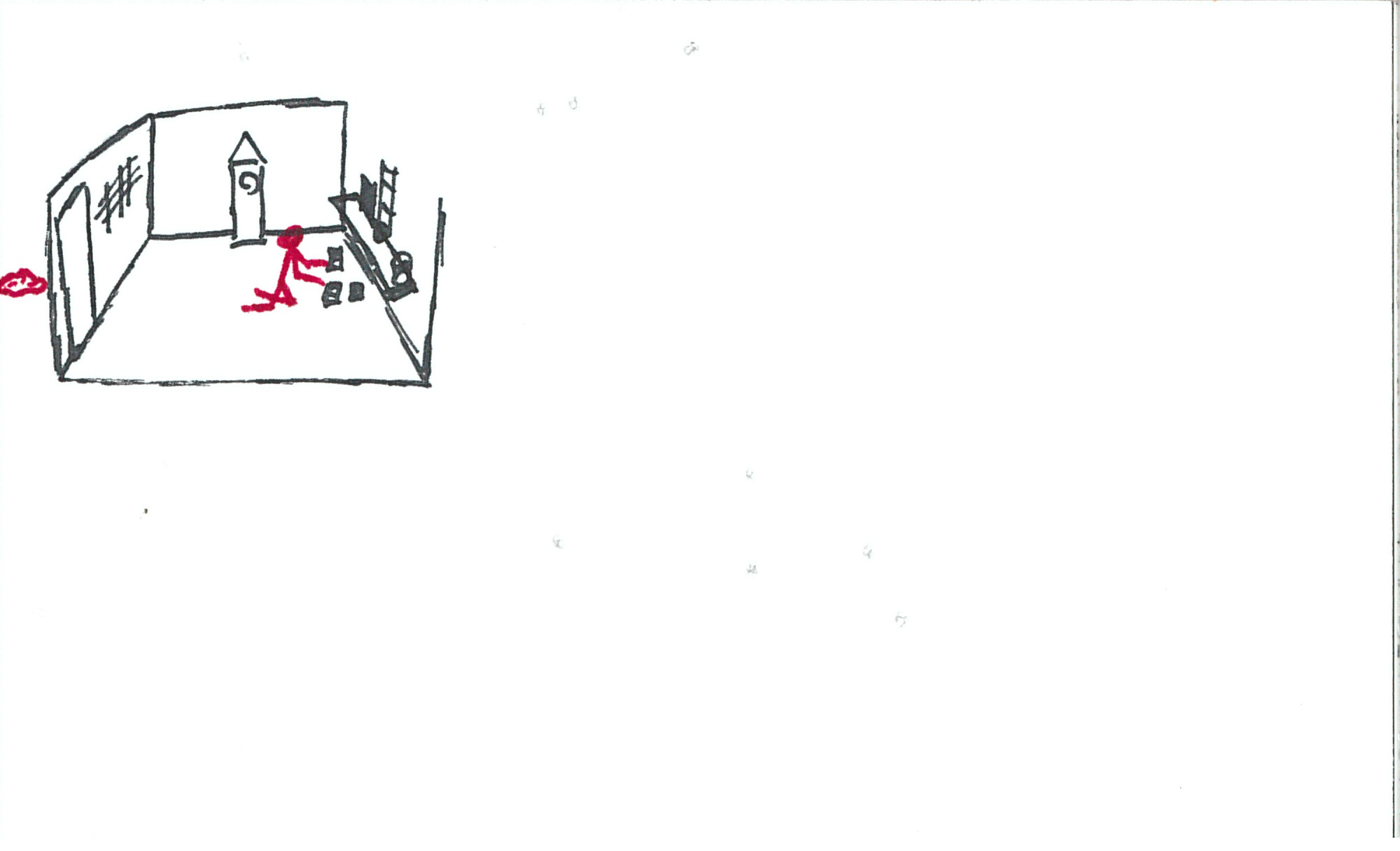
All the work orders that were backed up come spilling out, and many of their trays are almost through the conveyor belt.

somniat-storyboard-panel-20

The user scrambles to fulfill all the orders, but they have virtually no resources.

somniat-storyboard-panel-21

somniat-storyboard-panel-22

somniat-storyboard-panel-23

Everyone’s really unhappy with the user’s work.

somniat-storyboard-panel-24

No further work orders come after that onslaught.  The clock has ticked over back to “nighttime”.

somniat-storyboard-panel-25

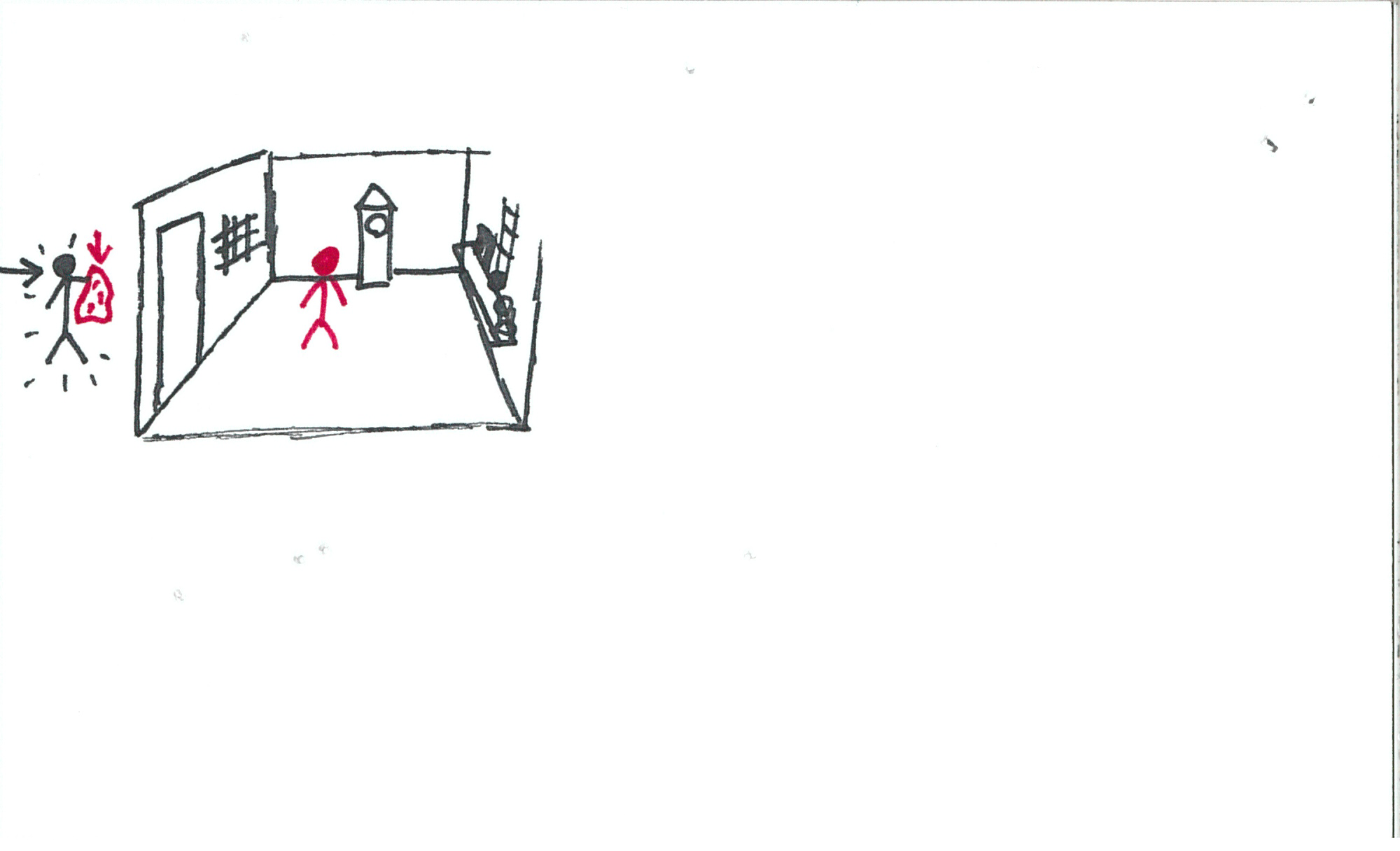
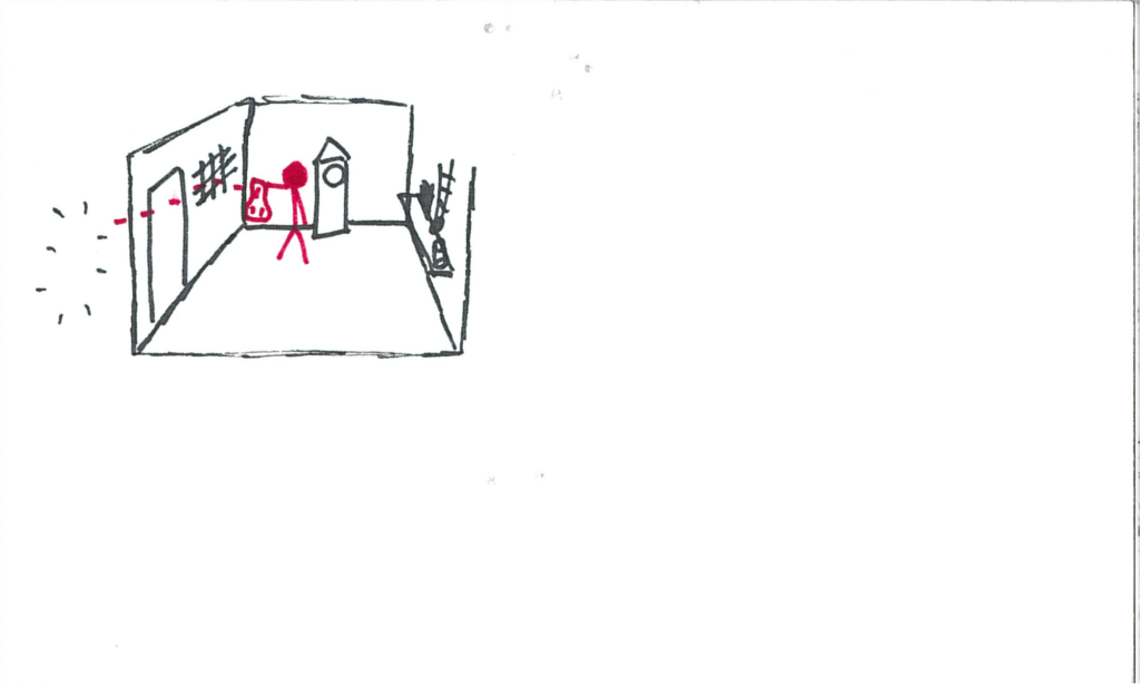
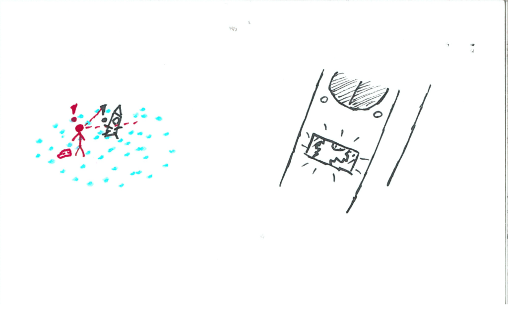
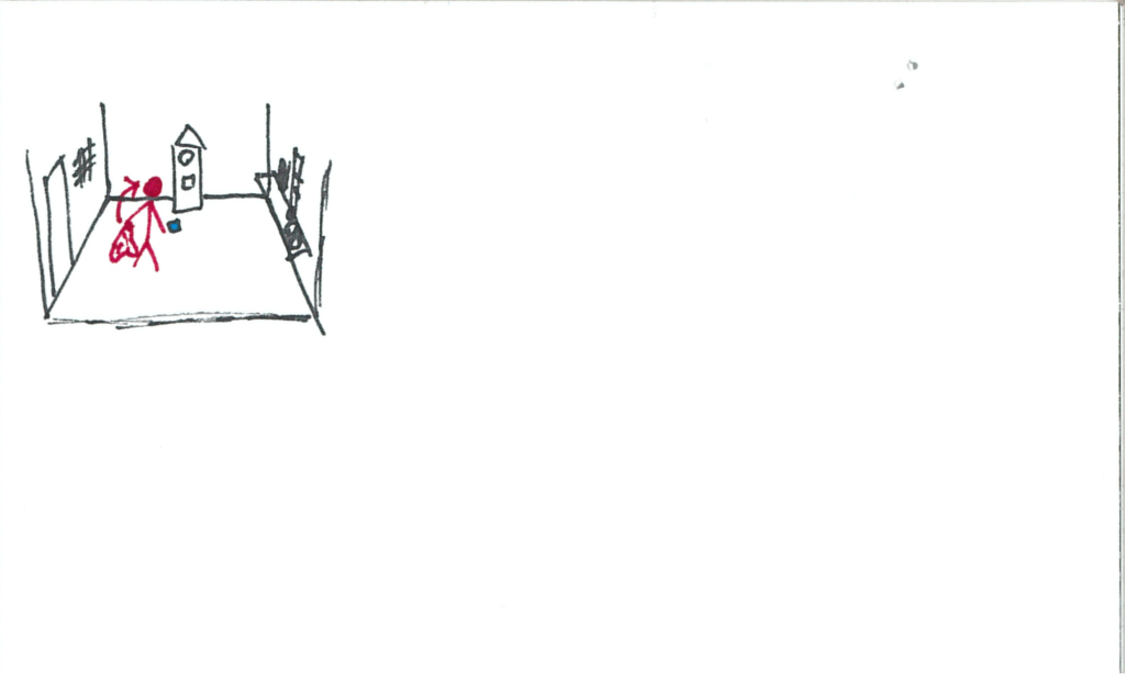
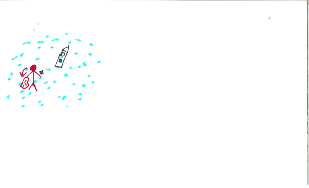
Upon looking at the blanket, it is picked up by an invisible force!

somniat-storyboard-panel-26

Once lowered, a person is revealed to now be holding it!  This person makes eye contact with the user and walks the blanket over to the window, offering it to the user.

somniat-storyboard-panel-27

Upon taking the blanket, it falls limp in the user’s hands and the unknown person is nowhere to be seen!

somniat-storyboard-panel-28

The blanket has some curious visual behaviours to it, encouraging the user to look at it up close.

somniat-storyboard-panel-29

Eventually the user will fill their entire field of view with the blanket upon investigating (this is drawn as pulling the blanket over the user’s head).

somniat-storyboard-panel-30

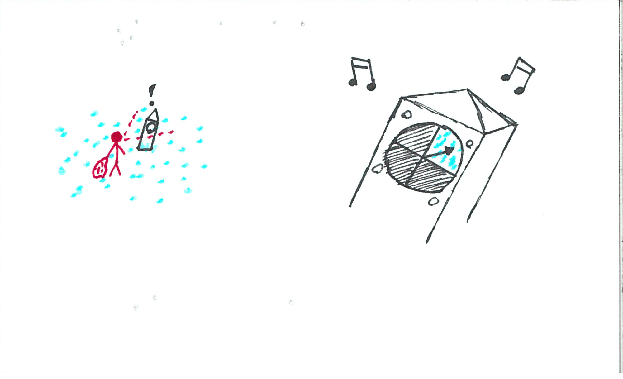
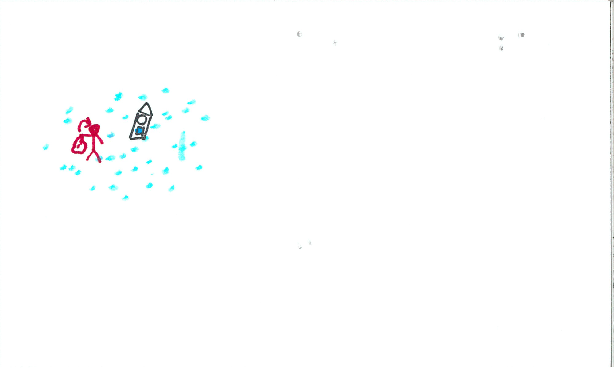
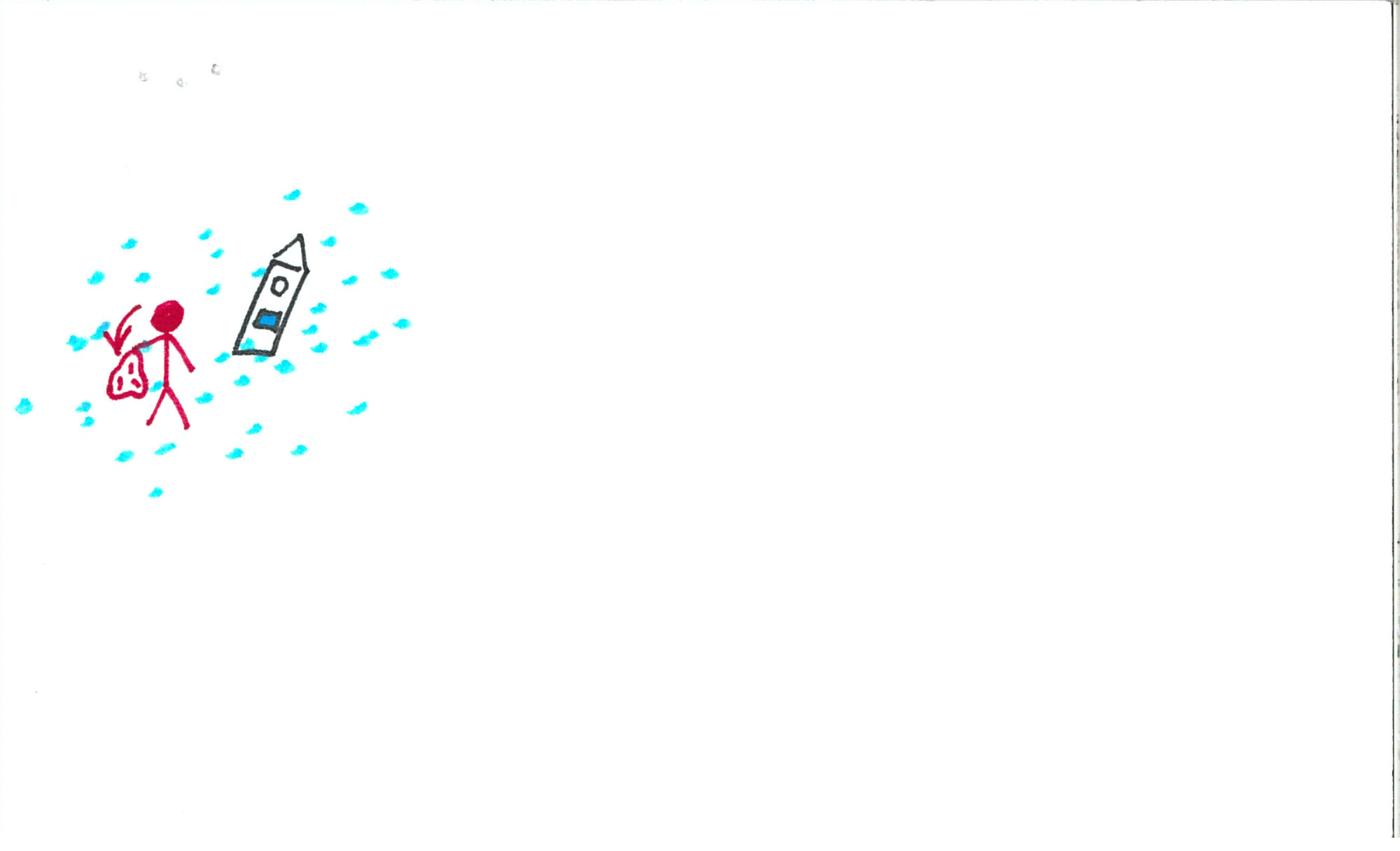
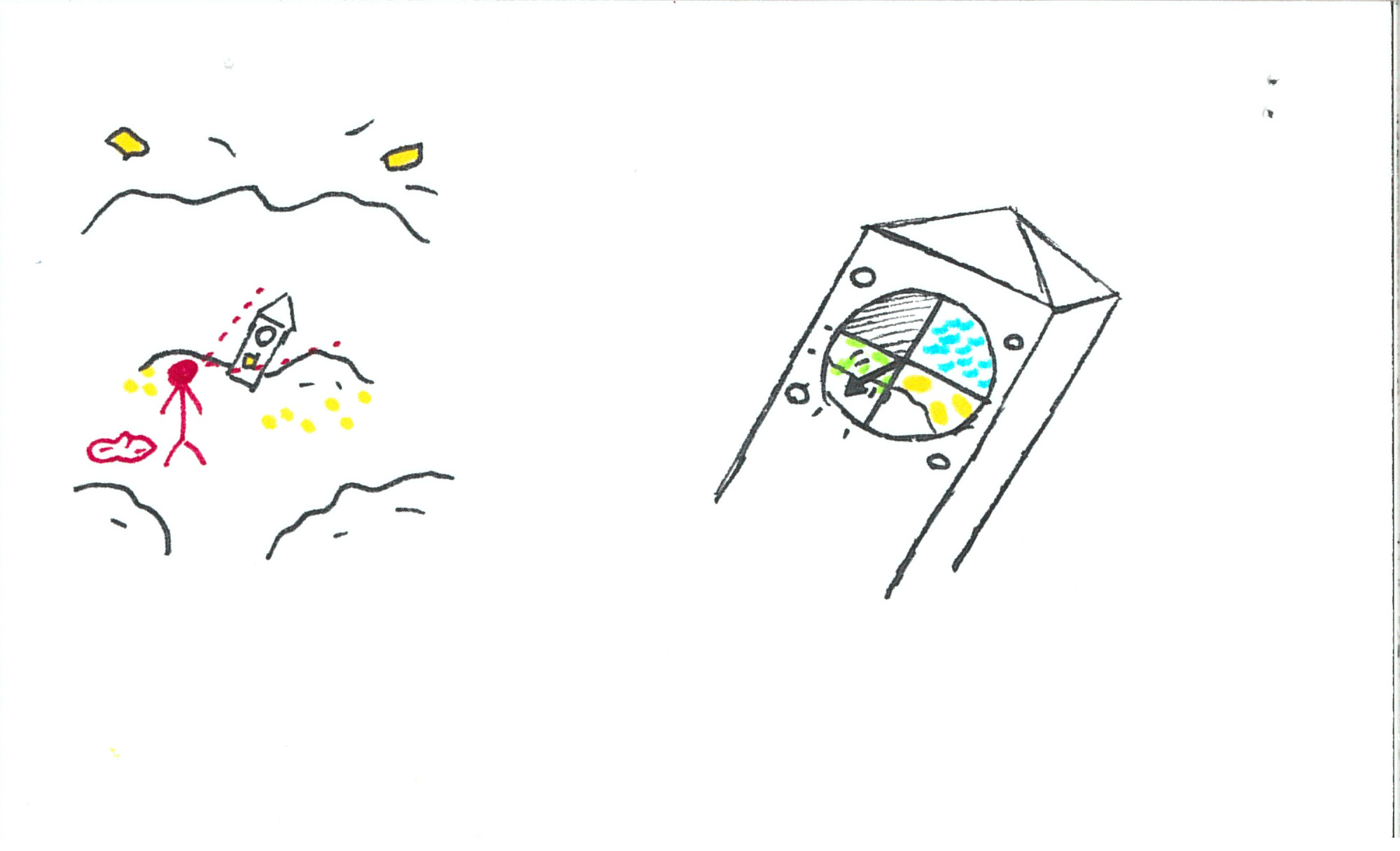
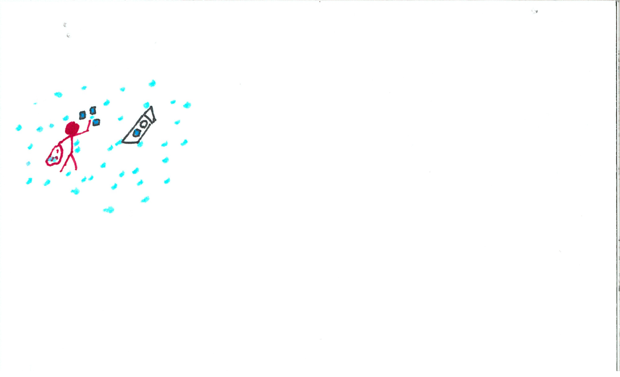
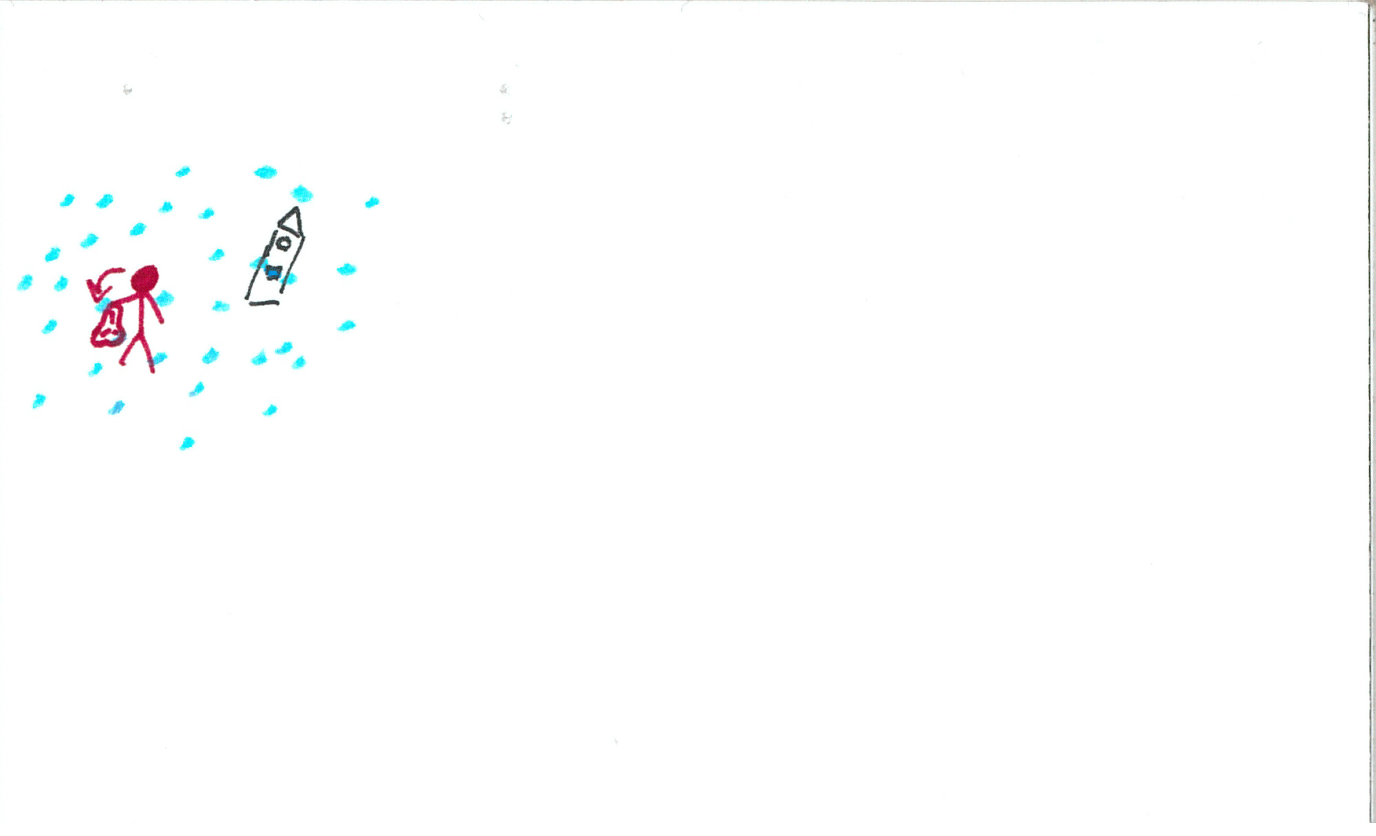
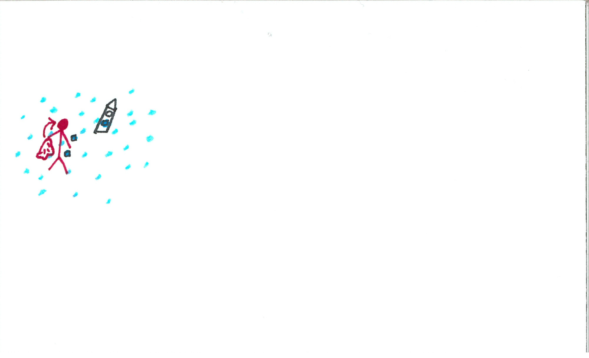
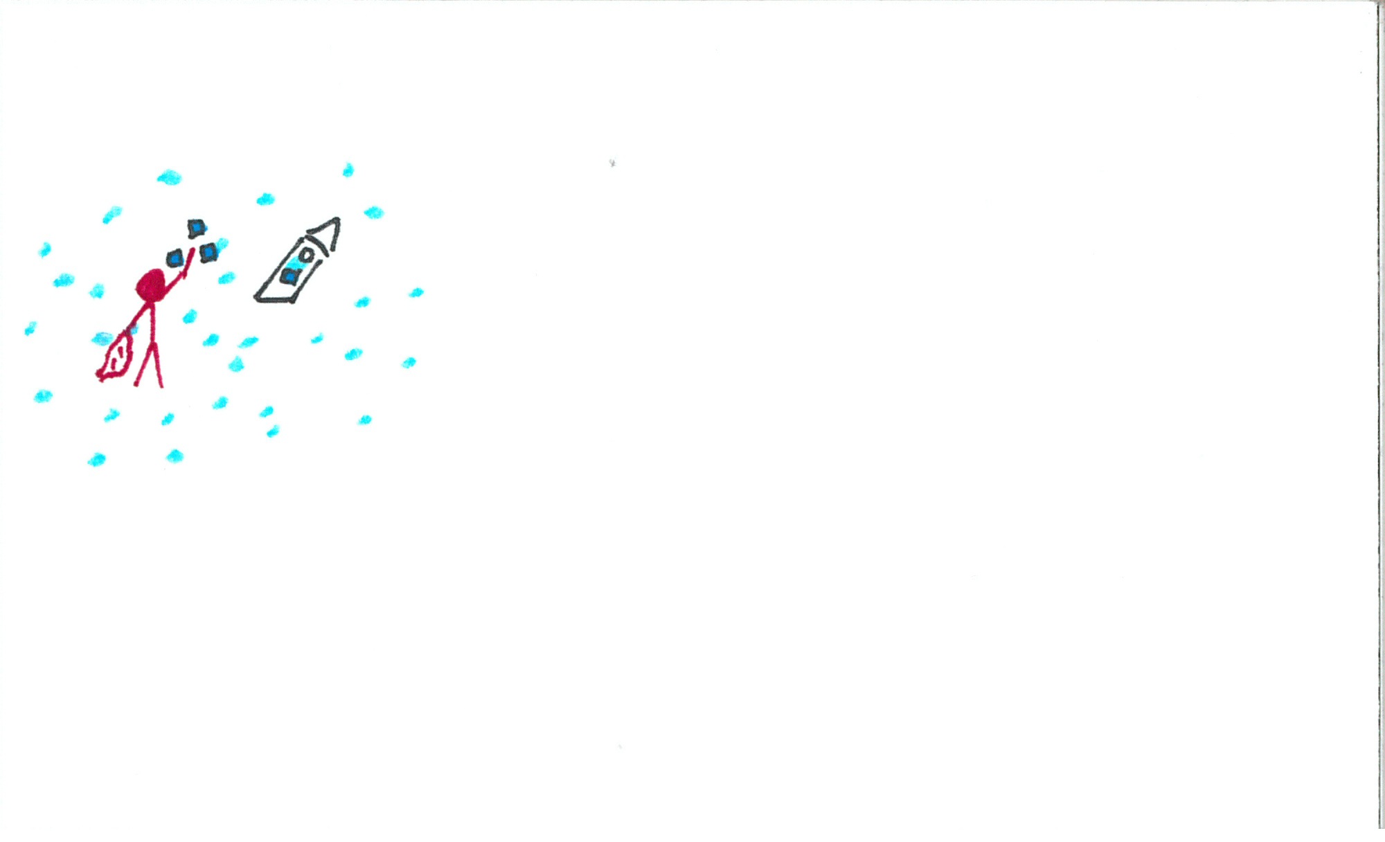
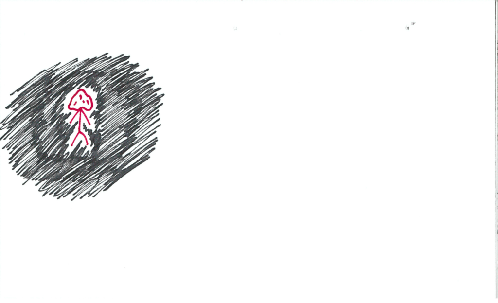
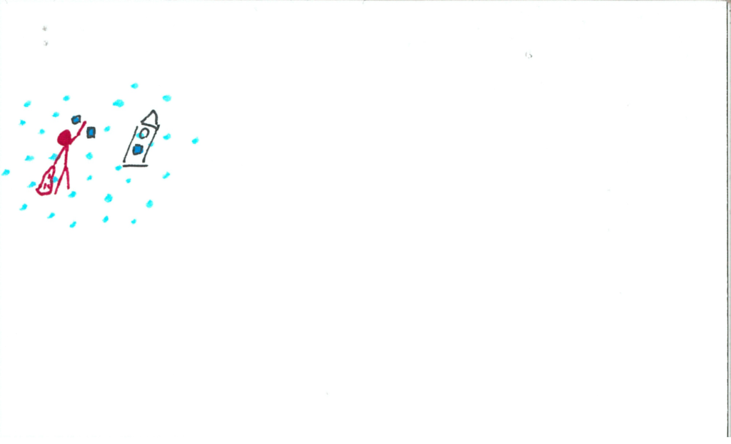
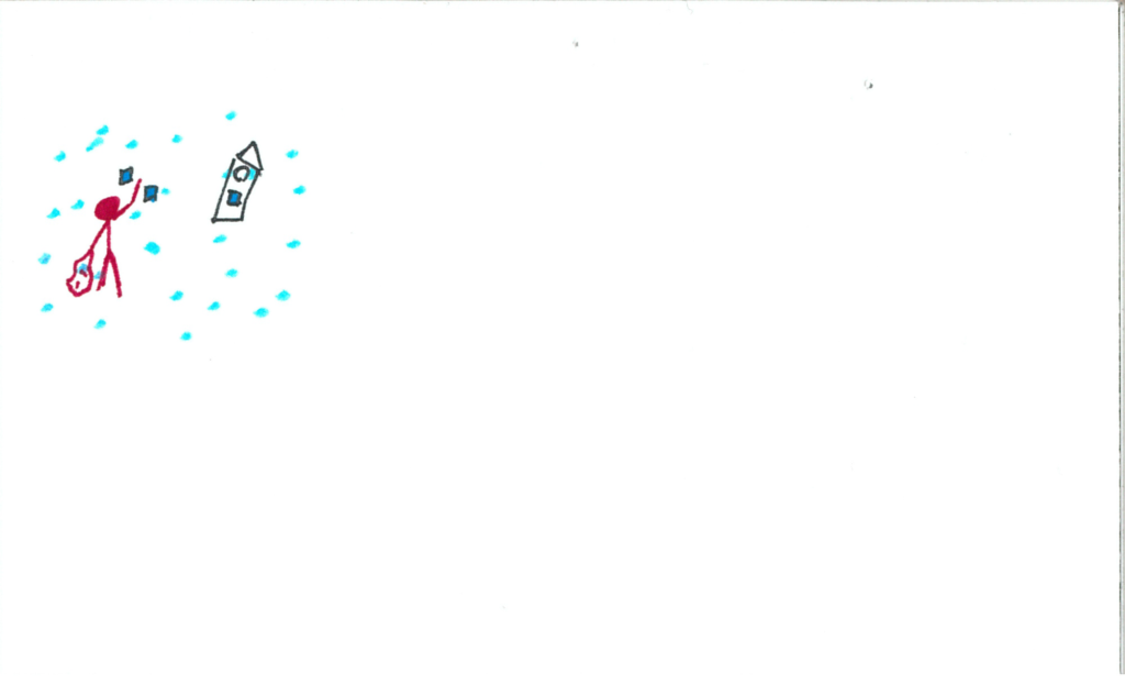
Upon removing/lowering the blanket, the user will find themselves in a magical world!  The same tune from the opening credits will begin to play.  This world will be in an expansive void with floating luminescent particles.  The grandfather clock is still front and centre.

somniat-storyboard-panel-31

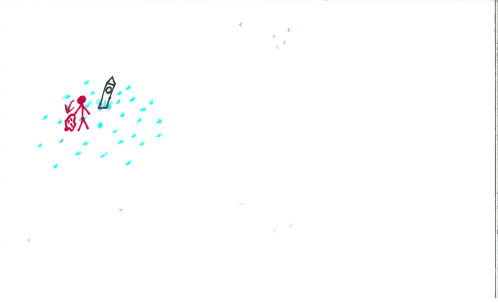
The clock chimes again.  The face is different now.  The hand is pointed to a drawing of this world, and there are three other portions which are unlit.

somniat-storyboard-panel-32

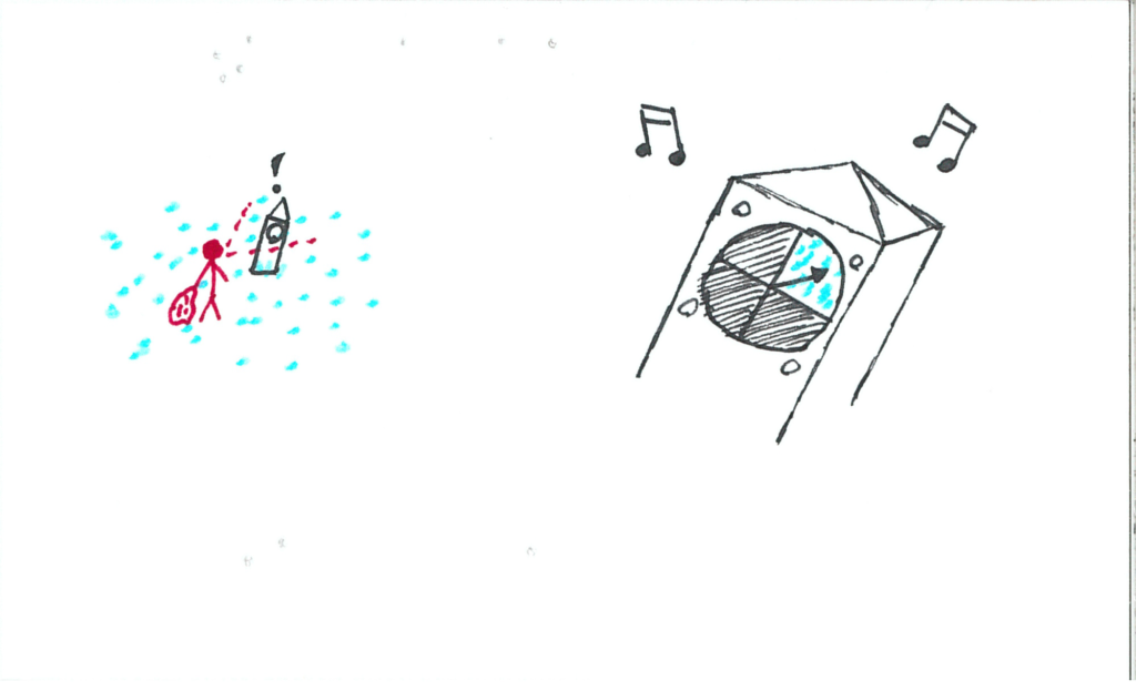
The energy source to the clock bursts.  It is now dimly lit blue.

somniat-storyboard-panel-33

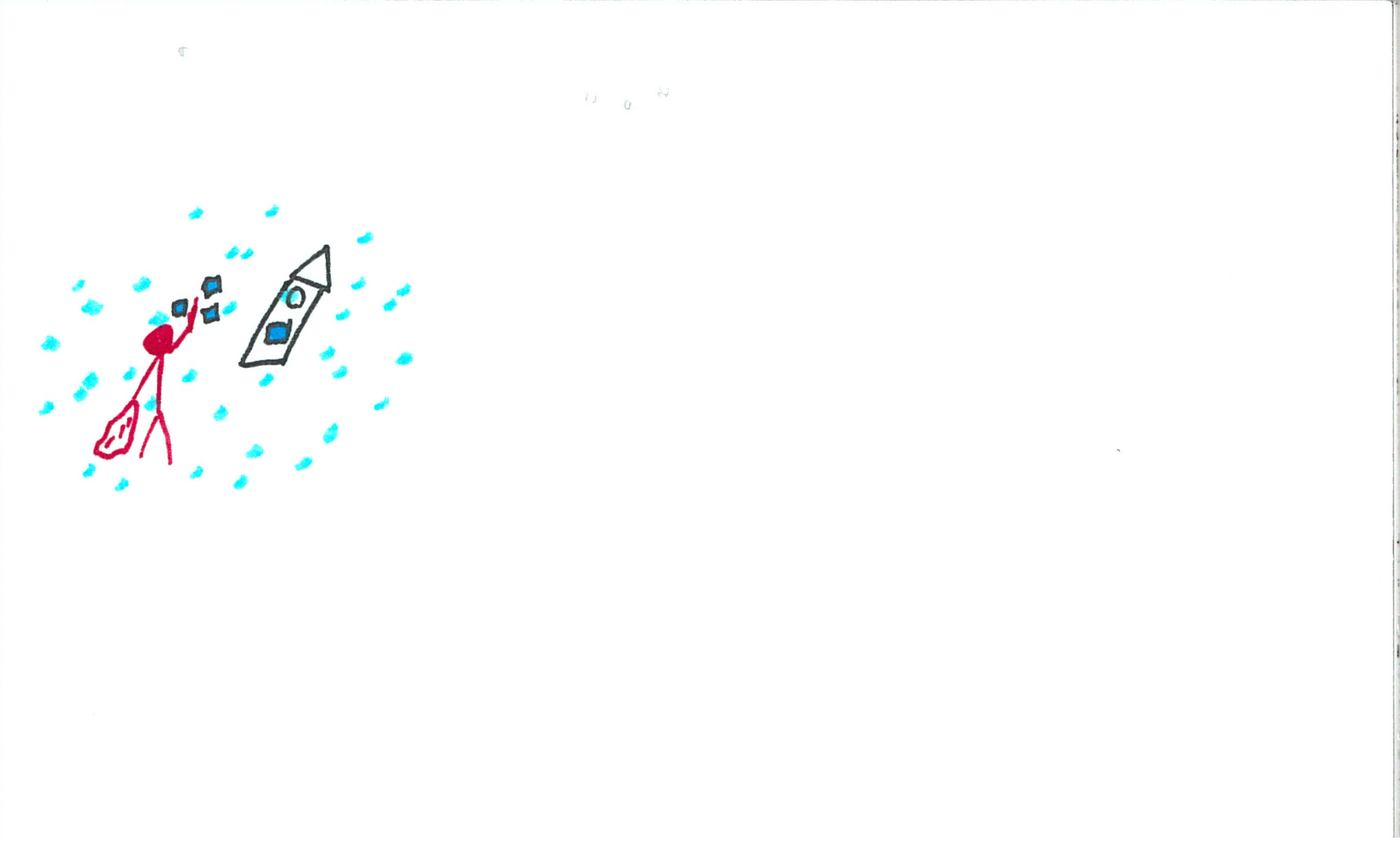
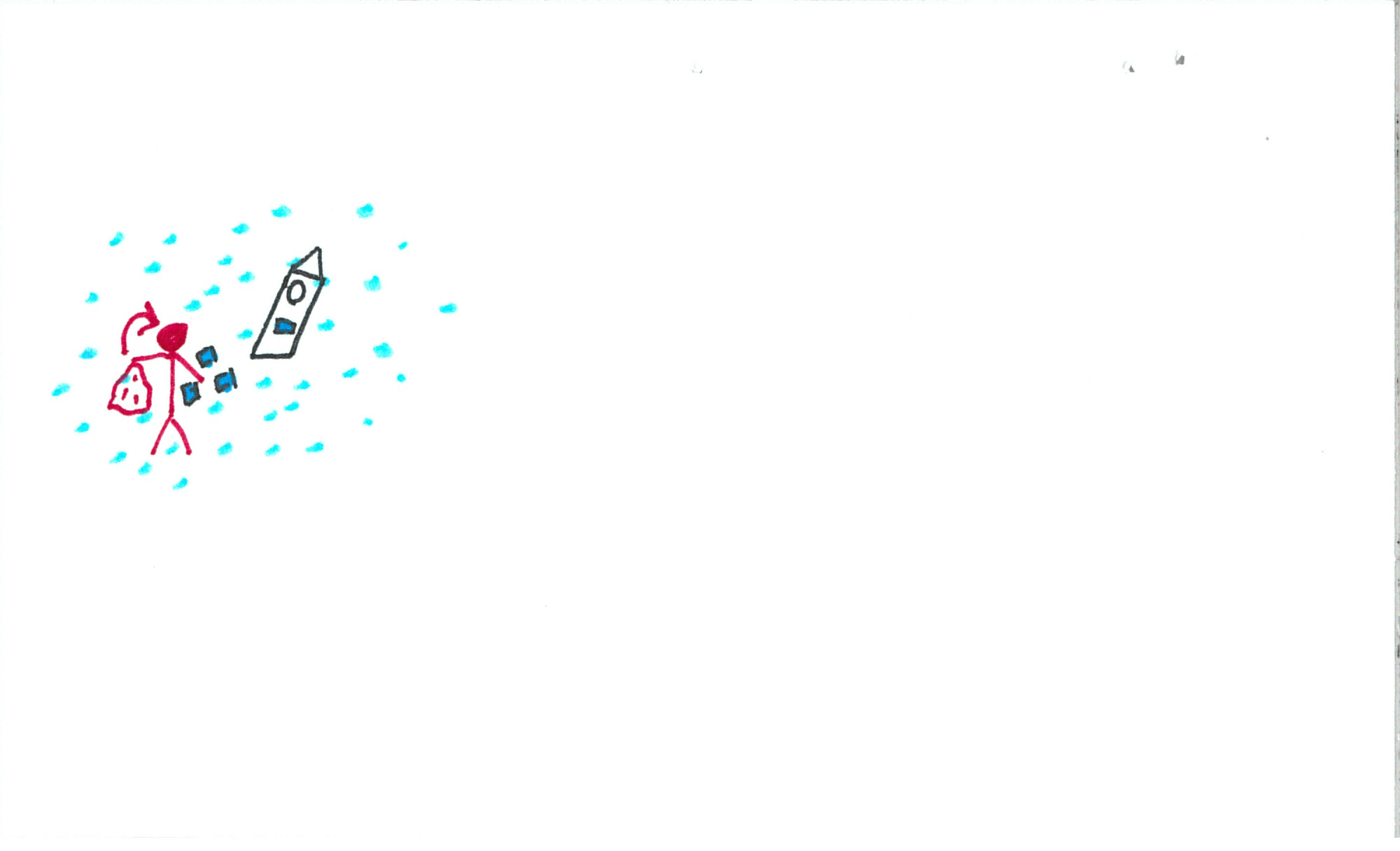
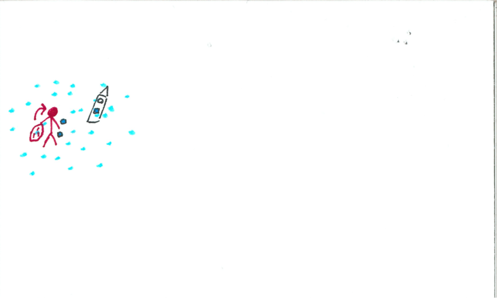
Eventually the user will interact with a particle.  The particle will start revolving around their controller.

somniat-storyboard-panel-34

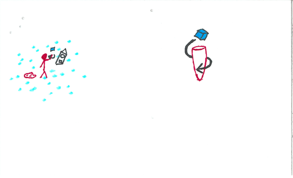
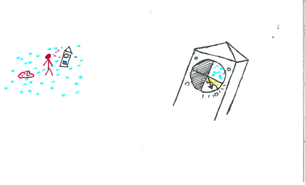
The user will insert the particle into the clock’s slot.

somniat-storyboard-panel-35

The music picks up.  A new section of the clock face illuminates!  The user will press the button next to that face (also illuminated), and the hand will tick to that location.

somniat-storyboard-panel-36

The user will block their view again with the blanket.

somniat-storyboard-panel-37

somniat-storyboard-panel-38

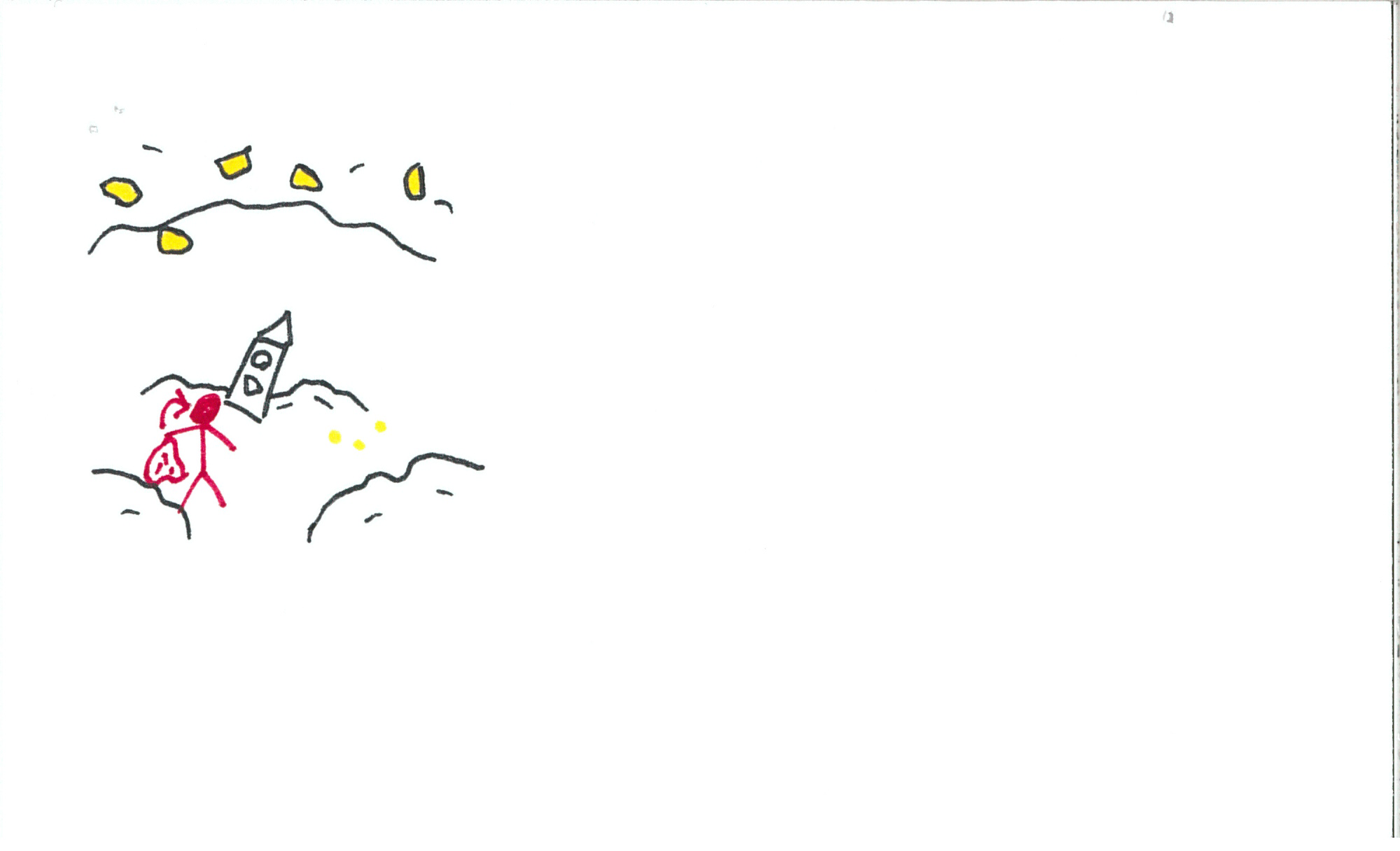
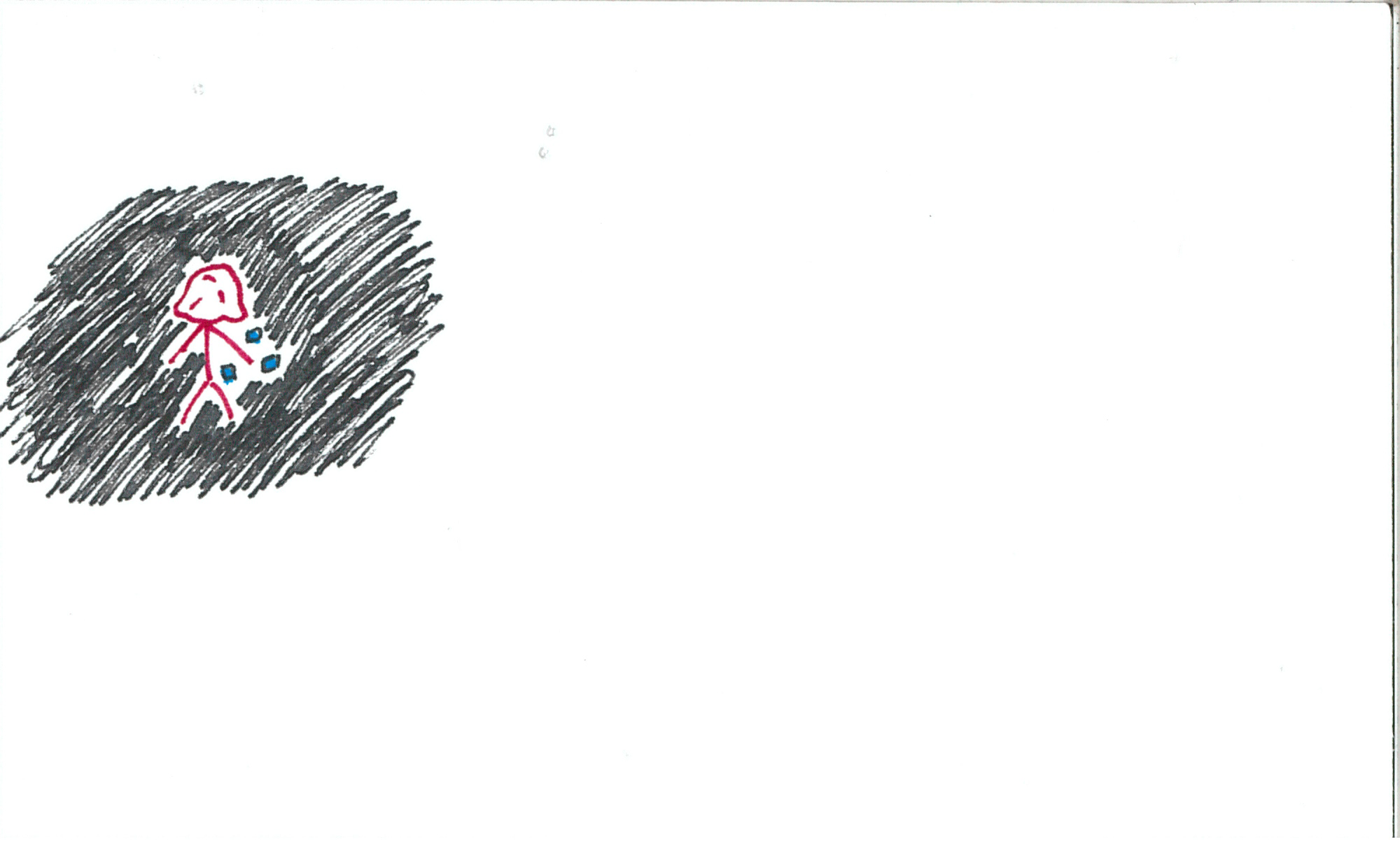
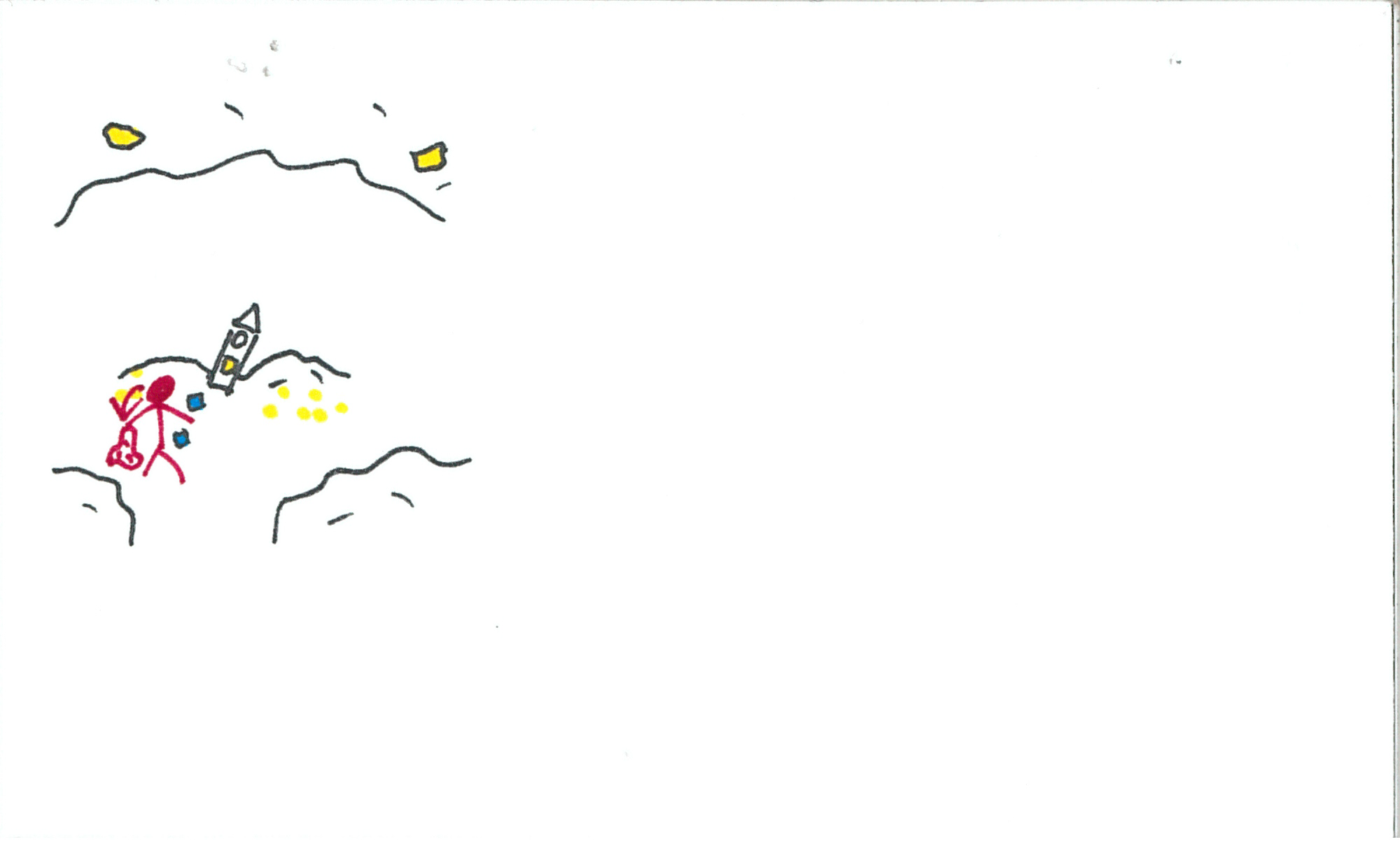
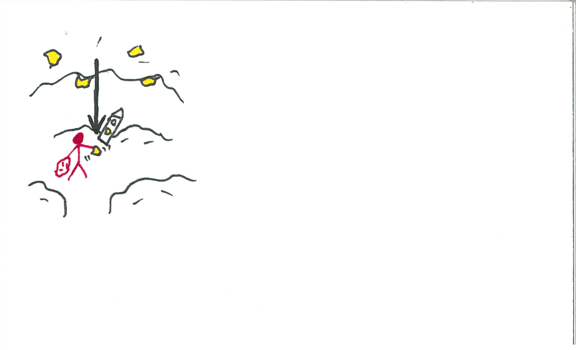
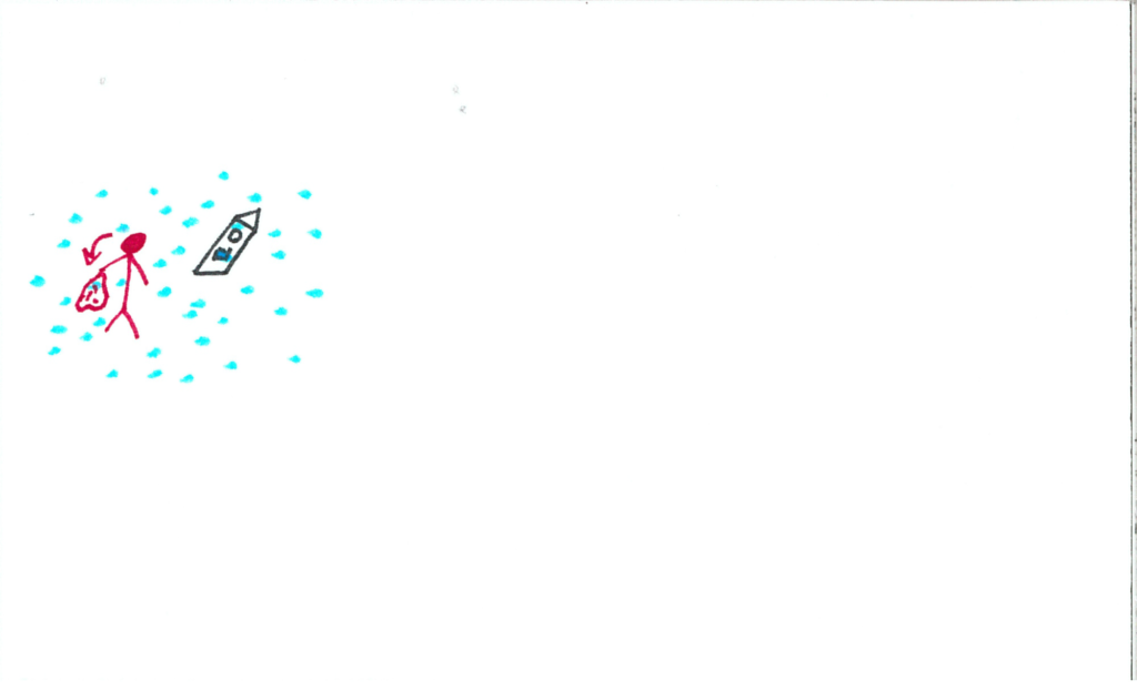
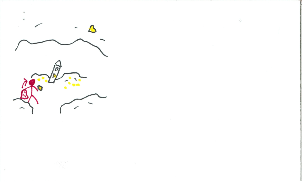
Upon removing/lowering the blanket, the user will find themselves in a cave.  There are luminescent crystals in the ceiling, and the clock’s slot is dimly lit their colour.  A particle came with the user when changing worlds, and floats up to the ceiling.  Clock is still front and centre.

somniat-storyboard-panel-39

The particle bumps a crystal.

somniat-storyboard-panel-40

The crystal falls and shatters on the ground.

somniat-storyboard-panel-41

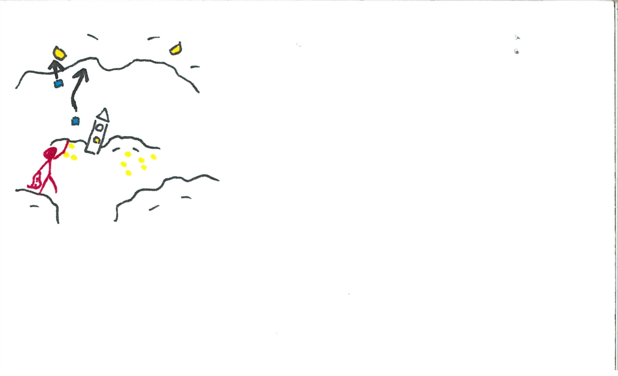
The user will eventually identify they need a way to safely acquire a crystal to insert into the clock, and so they will return to the particle void.

somniat-storyboard-panel-42

somniat-storyboard-panel-43

somniat-storyboard-panel-44

The user will grab a few particles and return to the cave.

somniat-storyboard-panel-45

somniat-storyboard-panel-46

somniat-storyboard-panel-47

somniat-storyboard-panel-48

somniat-storyboard-panel-49

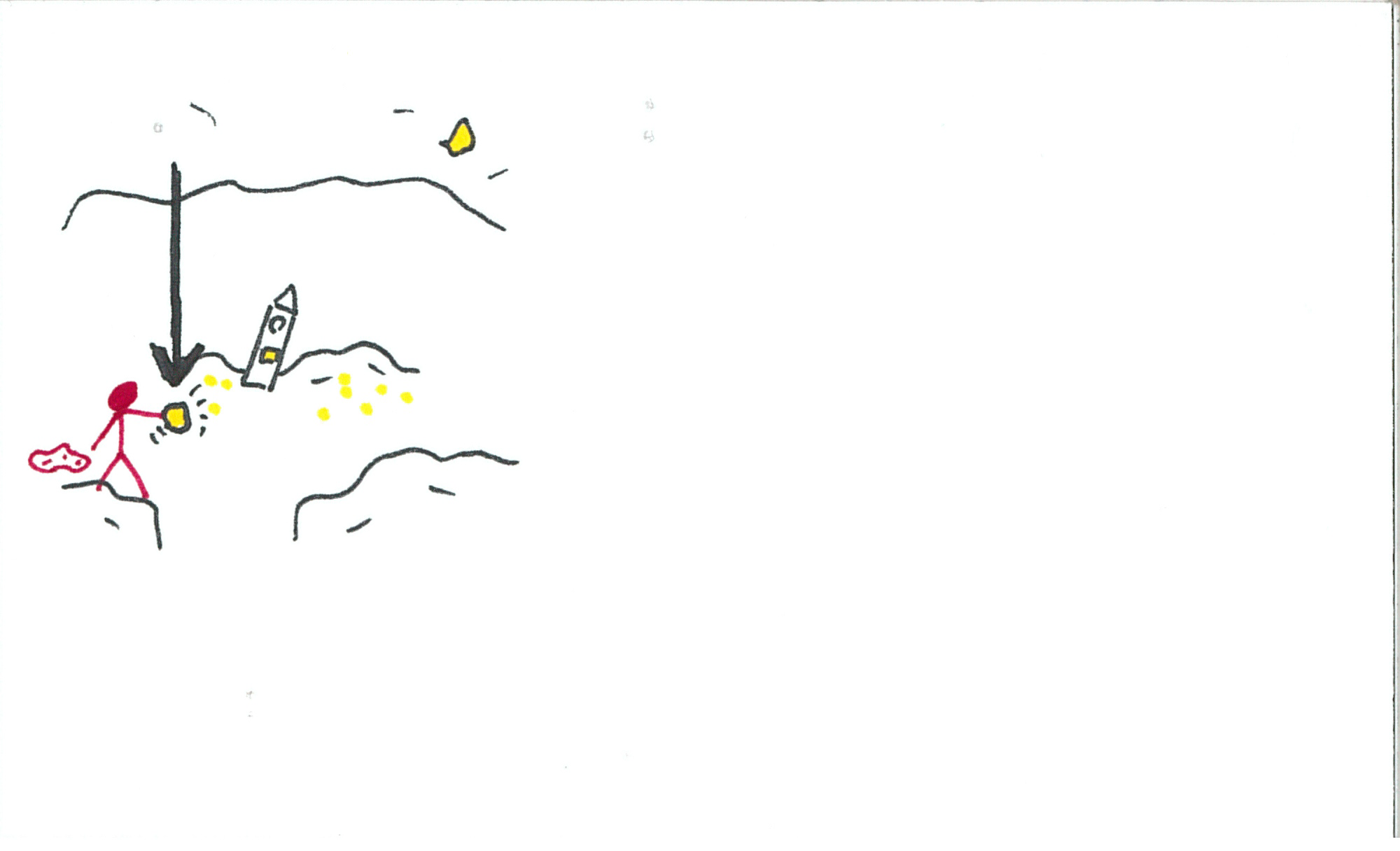
The user will catch one of the crystals as it falls, preventing it from shattering.  *Note: The crystals will replenish.  I draw them as finite sources, but for the game-sake of the experience, they will respawn between visits.

somniat-storyboard-panel-50

The user inserts the crystal into the clock.  Music picks up again.

somniat-storyboard-panel-51

A new section of the face illuminates, along with its button.  The user hits the button and the hand ticks over.

somniat-storyboard-panel-52

somniat-storyboard-panel-53

somniat-storyboard-panel-54

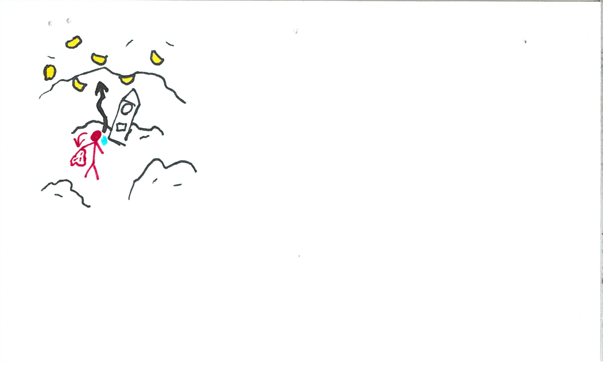
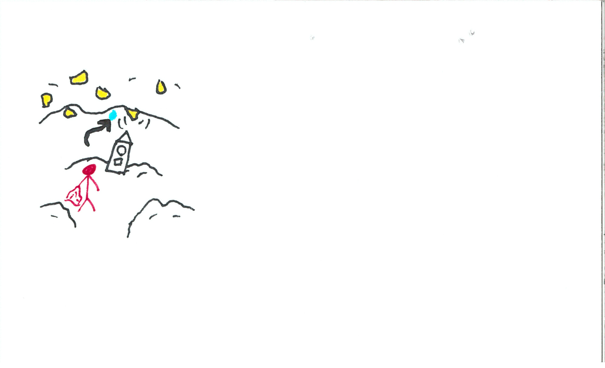
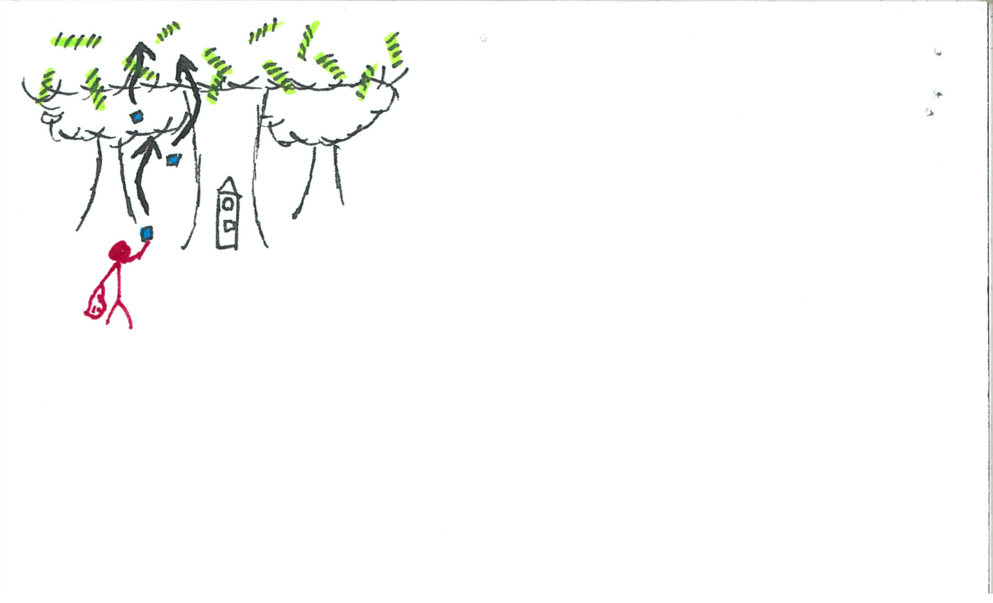
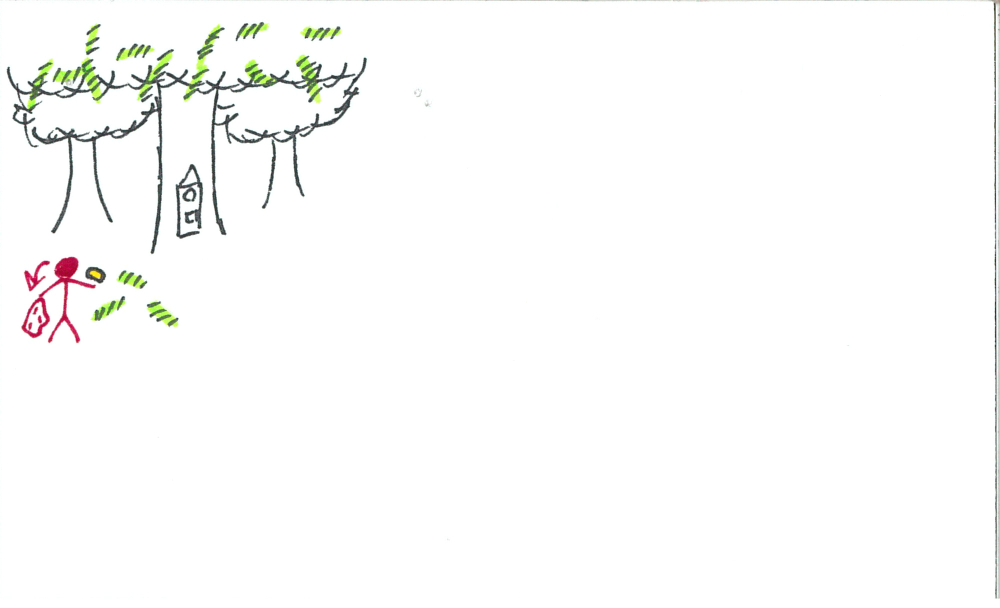
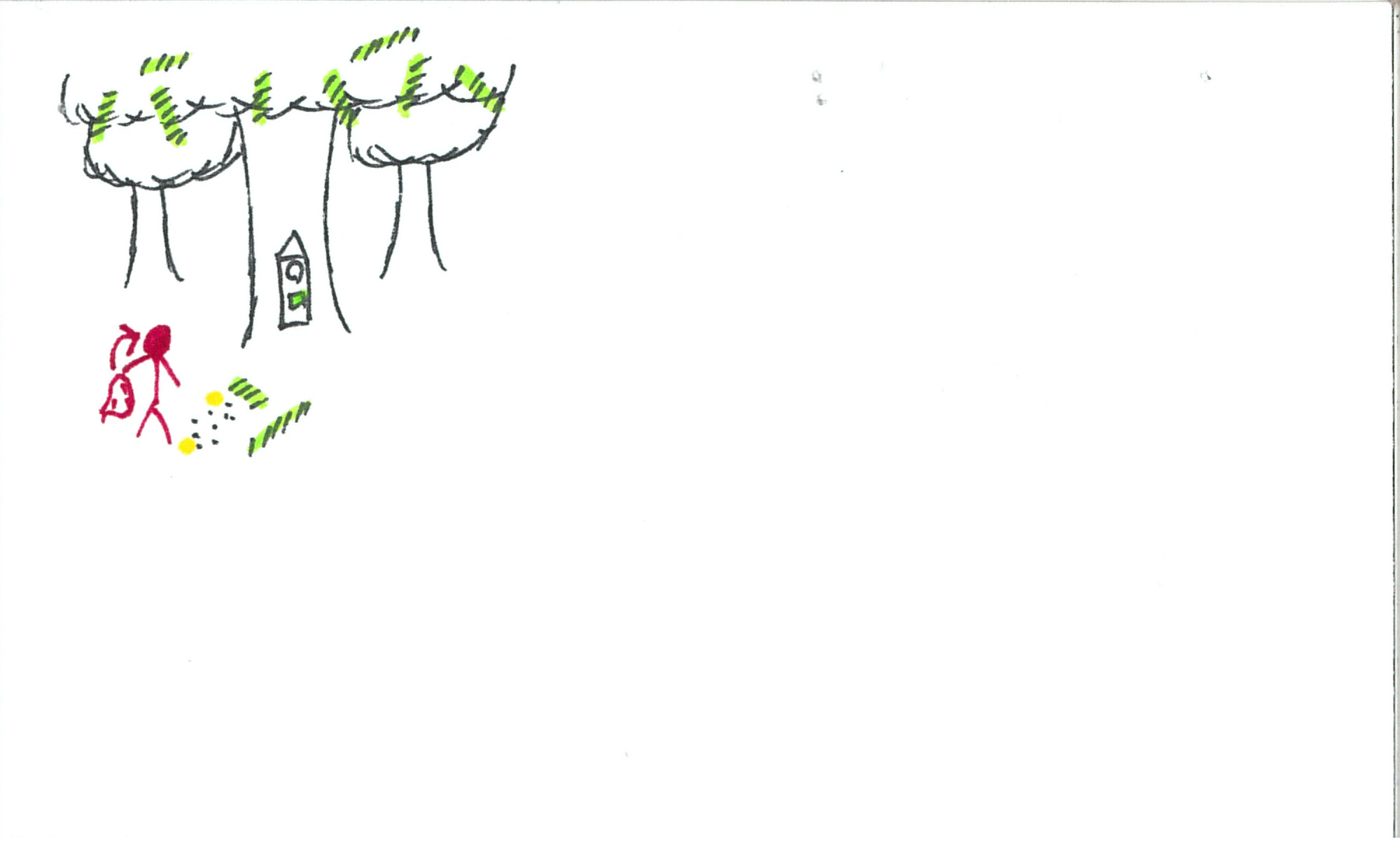
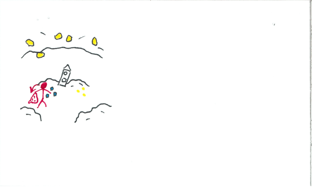
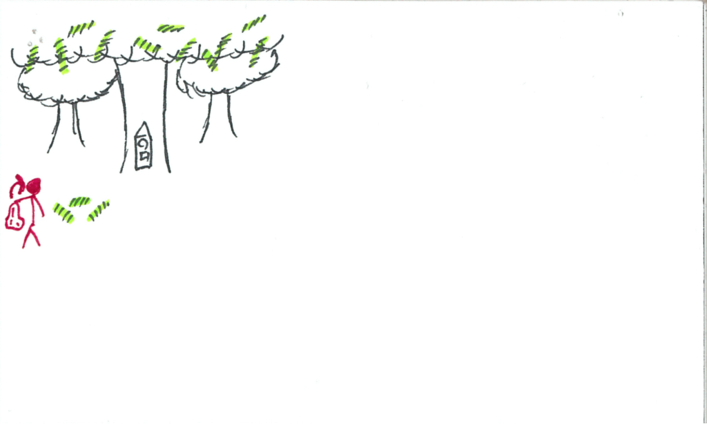
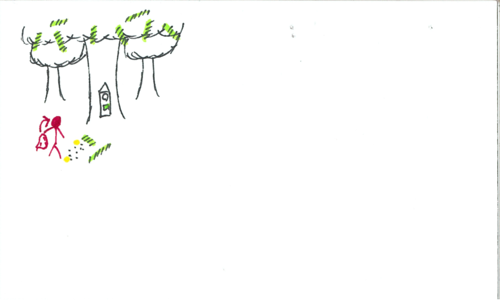
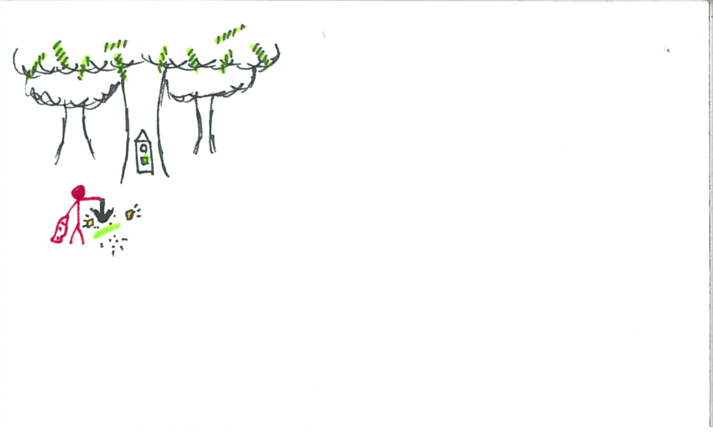
The user now finds themselves in a massive forest.  The clock is dimly lit green.  There are luminescent green objects in the trees.  The grandfather clock is front and centre as usual, this time inside a tree trunk.

somniat-storyboard-panel-55

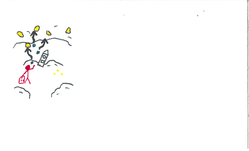
The user heads back to the particle void.

somniat-storyboard-panel-56

somniat-storyboard-panel-57

somniat-storyboard-panel-58

somniat-storyboard-panel-59

somniat-storyboard-panel-60

somniat-storyboard-panel-61

somniat-storyboard-panel-62

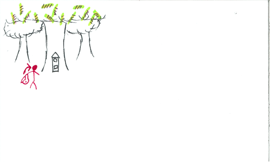
The user releases the particles into the trees.

somniat-storyboard-panel-63

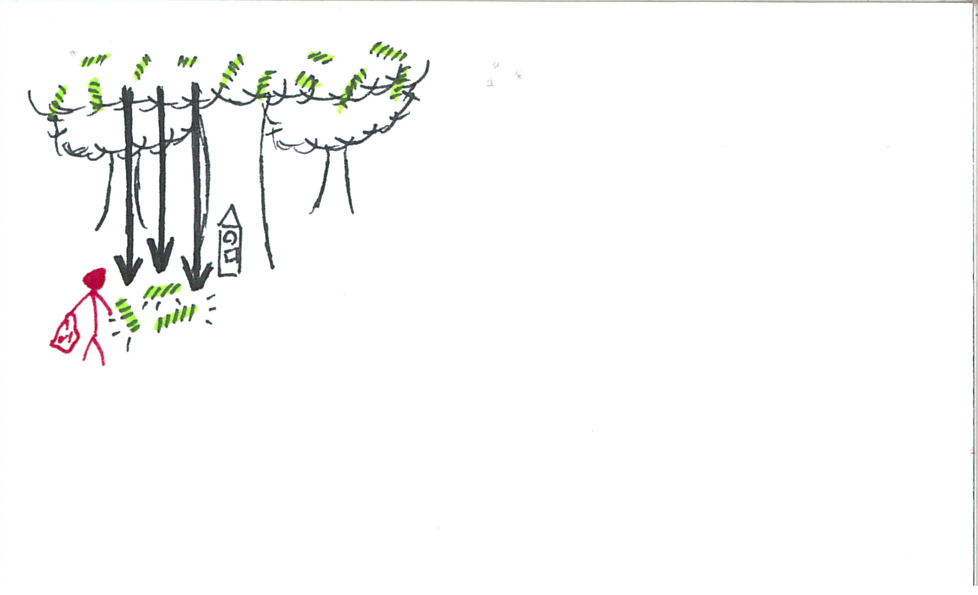
The luminescent sticks fall to the ground, but are encased in an outer shell.

somniat-storyboard-panel-64

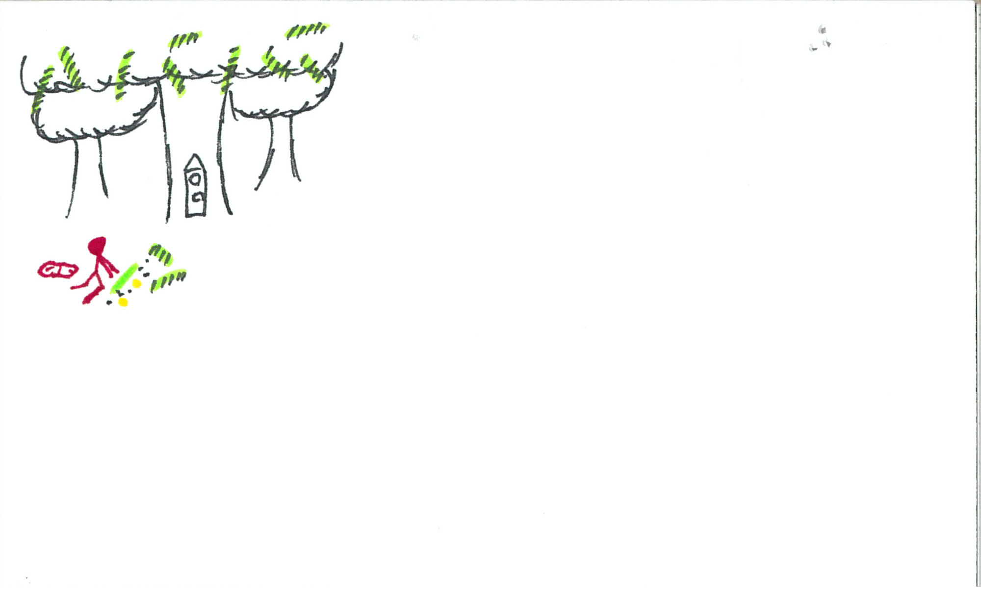
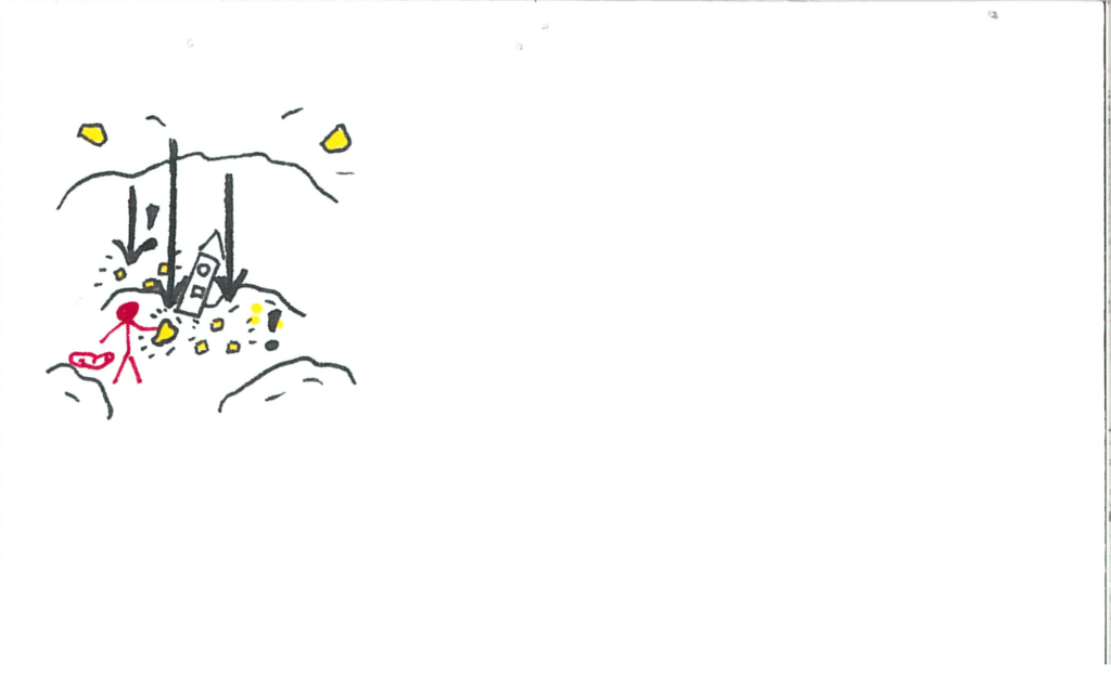
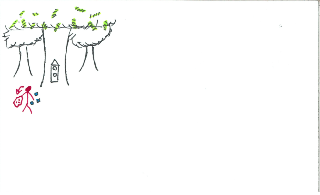
The user now needs a way to break open the shells.  The user goes to get a crystal.

somniat-storyboard-panel-65

somniat-storyboard-panel-66

somniat-storyboard-panel-67

somniat-storyboard-panel-68


somniat-storyboard-panel-69

somniat-storyboard-panel-70

somniat-storyboard-panel-71

somniat-storyboard-panel-72

somniat-storyboard-panel-73

somniat-storyboard-panel-74

somniat-storyboard-panel-75

somniat-storyboard-panel-76

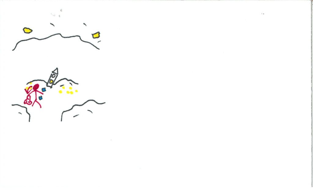
The user drops the crystal onto a shell.  The crystal and the shell shatter, revealing the luminescent stick.

somniat-storyboard-panel-77

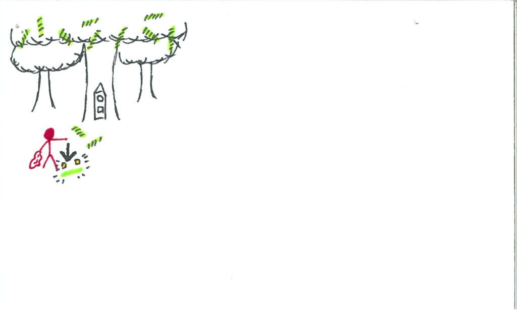
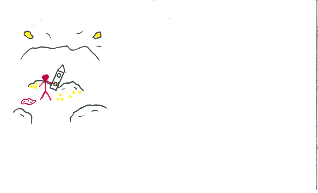
The user grabs the stick.

somniat-storyboard-panel-78

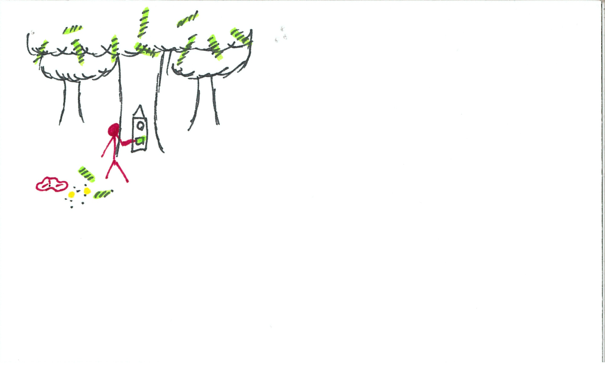
The user inserts the stick into the clock.  Music picks up once more.

somniat-storyboard-panel-79

The clock illuminates its final face, a bright white light.  The user hits the button and the hand ticks over.

somniat-storyboard-panel-80

The user goes to this mystery world.

somniat-storyboard-panel-81

somniat-storyboard-panel-82

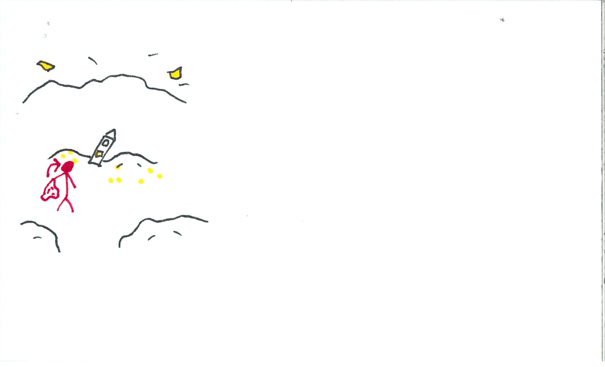
Upon removing/lowering the blanket, the music abruptly and uncomfortably stops.  The user is back in the workroom.

somniat-storyboard-panel-83

The work whistle blows.

somniat-storyboard-panel-84

A tag comes down the pipe.

somniat-storyboard-panel-85

It requests resources that the user certainly does not have; specifically cubes.

somniat-storyboard-panel-86

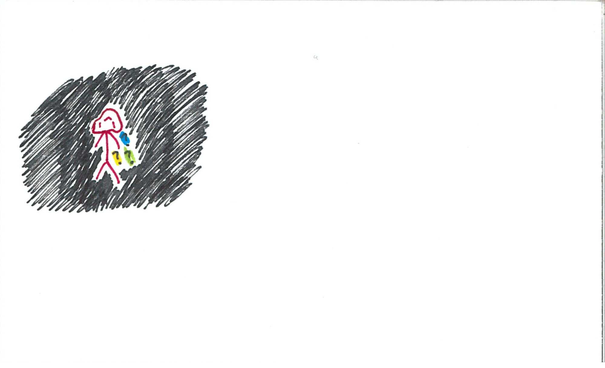
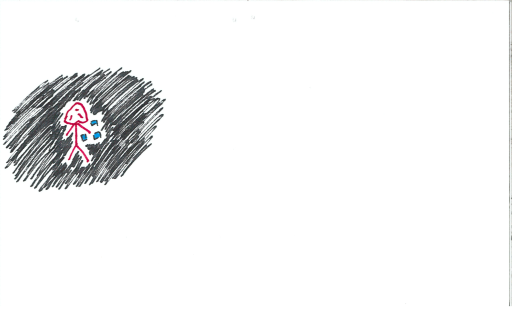
However, upon looking at their controller, they have a blue particle still revolving around it!  Note: these particles are cubes.

somniat-storyboard-panel-87

The user goes back to the particle void to collect more particle cubes.

somniat-storyboard-panel-88

somniat-storyboard-panel-89

somniat-storyboard-panel-90

somniat-storyboard-panel-91

somniat-storyboard-panel-92

somniat-storyboard-panel-93

somniat-storyboard-panel-94

The user fulfills the order with the magical cubes.

somniat-storyboard-panel-95

somniat-storyboard-panel-96

The customer is happier than any customer before!

somniat-storyboard-panel-97

Another order arrives.  It’s a doozy!  The order requests all of the resources.

somniat-storyboard-panel-98

The user knows what to do!  They go to each realm to gather the necessary resources.

somniat-storyboard-panel-99

somniat-storyboard-panel-100

somniat-storyboard-panel-101

somniat-storyboard-panel-102

somniat-storyboard-panel-103

somniat-storyboard-panel-104

The user assembles the complete order with all their magical items.

somniat-storyboard-panel-105

The same yellow orb from the opening falls into the money jar.

somniat-storyboard-panel-106

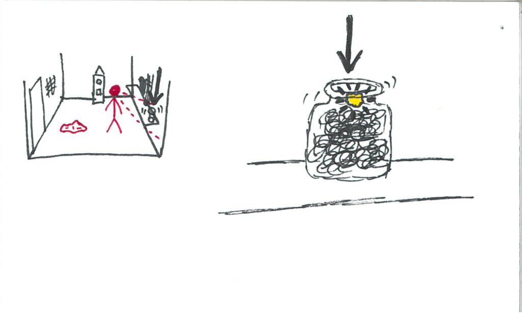
The user grabs the orb.  The clock is dimly glowing yellow.

somniat-storyboard-panel-107

The user inserts the orb into the clock.

somniat-storyboard-panel-108

The music pleasantly resumes, as the room fades out to black, leaving the user and the clock together in darkness.

somniat-storyboard-panel-109

Roll credits!

somniat-storyboard-panel-110


So!  That is Somniat :)  I’d love to hear what you all think of this idea.  Shouldn’t be too long before it’s a full experience and we can give it a go!

As I complete developing this narrative, I’ll continue sharing my experience here.  If you have any questions or feedback (I love feedback!), I’d love to hear about it in the comments or in an email to blog@talariavr.com.  Should be getting back into hardware topics soon :)

SteamVR Tracking License Day 3

SteamVR Tracking License Day 3

Render Model

In our third and final day, we started out with creating our own render models for the reference objects given to us in our hardware development kit.  Synapse taught the course using open-source software, namely Blender.  After successfully modelling/downloading our render models (which included Thor’s hammer, a longsword, a Portal gun, and more), we tossed them into our SteamVR render models folder.  If you want to change up some render models yourself, take a look at the format of them.  Should be under:
Steam\steamapps\common\SteamVR\resources\rendermodels\
All it needs is an obj (same name as the folder) with forward pointing in the -z, a material file, and a texture file.  That’s the format for any SteamVR Tracked object (so third party controllers like Oculus Touch may not work under that format).  I’m not sure if this will throw any errors when trying to launch experiences, so it might be smart to make a backup if you plan on messing with any of these files!

Practice

So now Synapse wanted to be sure that we have what it takes to design tracked objects, and fix any problems that may arise.  We were given various broken situations (ie. IMU axes inverted, sensors reporting incorrect positions, incorrect IDs, etc.), and then troubleshot them into correction.  These activities were done on “UFOs” provided by Synapse (not included in our Hardware Development Kit).  They were pretty much versatile tracked objects that we would select which sensors were active and then play around with its JSON file.  After successfully troubleshooting the UFO problems, we spent some time experimented with activating various sensors on the UFO and observing its effect on tracking.   It was pretty cool – we limited sensors to be only colinear or coplanar, and were able to experience pose rotation and translation error in real-time (was most evident when disabling the IMU)!  Always cool to see theory come out in application.

Architecture

We then went over the electrical architecture and firmware technicalities.  There’s not really much that I can say here, other than reiterate that Valve has made the decision to have Synapse lock down the firmware (and by extension a large amount of the bill of materials) to ensure a standard for the SteamVR Tracking ecosystem.  If you want more info, sign up to be a licensee!

Putting it all Together

And so we’ve finally got it all.  The sensor placement.  The visualization and optimization.  The JSON file.  The Watchman.  The render model.  Troubleshooting and low-level understanding.  We have the power to create a motion-tracked object with sub-millimeter accuracy in virtual reality.  Bring it on.

With still an hour and half left in the day, and with training formally over, one of our colleagues was eager to go through the full process (and we were happy to join in the fun).  Ciuffo, the engineer from Synapse who was our amazing primary teacher for the course, ran off to his office and returned with an object that had plenty of variances in geometry to track: a Nerf gun (Photo credit again goes to Michael McClenaghan).

nerf-rifle-watchman

Michael was on hardware duty – he applied and wired up sensors, took physical measurements, and prepared the JSON.  You can read more about his experience on that here.  Our colleague Jack then assembled the render model, ensuring its orientation would match our physical device.  I was pretty eager to explore next-steps with this process, so I hopped into Unity and began preparing a scene.  Once our hour and a half was up, we had a system with impressively stable tracking (especially considering only 5 sensors +IMU were active), a properly aligned render model, and a successful “game” in Unity.


Needless to say, we were proud :)  Just goes to show how efficient Synapse and Valve have made the prototyping process.  (Also, sorry about the slow-motion; we accidentally recorded high-speed, but I think adds a slight charm to it).


Farewell Synapse

And thus concludes the epic journey that was SteamVR Tracking training.  To say I had an amazing time is an understatement, and I think my colleagues from the course would readily agree.  Synapse runs a great and creative environment, and I do hope I get to work with them again in the future.  Cheers, Synapse – keep up the amazing structure and work you have going for you.

If any of you from the community want to reach out, we’ve got comments and we’ve got email (blog@talariavr.com) – feel free to hit us up!  I’ll be summarizing the past three days in my next post, as well as answering any community questions that have rolled in since the training began.  Keeping this blog is a neat and new experience for me, and I hope I’m providing you all with information that’s valuable to you.  ‘Til next time!

SteamVR Tracking License Day 2

SteamVR Tracking License Day 2

Full Day

Alright!  Today was our first full on training day, and we did nothing but learn from 9:00 – 5:00; it was so amazing!  We’re all very much friends in the class at this point, cracking jokes and sharing ideas.  Synapse does a great job at creating a fantastic educational environment; I’d be eager to return here in the future if I ever have the opportunity.

Highlights for the second day are that we learned how to simulate and optimize sensor placement, and we’re all getting pretty good at knowing what to look out for when designing tracked objects so they are sure to have the best tracking.  Designing for lighthouse is very much a skill that comes with practice, and over time you develop an intuition for what will work best.

Simulation

So before diving into any physical hardware, Valve has created a magnificent visualization tool called HMD Designer.  It’s got a few different options, but ultimately you feed it a 3D .STL model and it will spit out possible optimized sensor positions and angles for the best quality of tracking.  Another thing you can do is feed it a .JSON file with the sensor positions already defined, but we’ll get into that later.

A great and key feature of HMD Designer is that it outputs multiple visualizations, primarily used to see how the lighthouse protocols interact with your object and its current sensor positions.  FYI, dense lighthouse science ahead.

HMD Designer Graphs

In this graphic (click to zoom), a 2D representation of how simulated tracking performs with your specific object helps tell us where any potential shortcomings of the current design may be.  The bluer, the better!  Also, regarding the format of these graphs, we are looking at unwrapped 3D visualizations (we’ll see the wrapped versions later).  The left and right outer edges are -Z, centre is +Z, top is +Y, bottom -Y, and central-left is -X, central-right +X.  If that doesn’t make sense, bear with me until the end of this section.

In the first graph, we see how many sensors can see the lighthouse at any given surface point of the object.  The more sensors visible, the more datapoints we get!  This is great because with more datapoints comes redundancy, and that really helps lock down a very definite pose.

In the second graph, we’ve got a heatmap of potential rotation errors.  These errors are caused by all visible sensors residing on a very similar plane (discussed briefly in Day 1), and because of that, SteamVR will have a very tough time negotiating minute changes of rotations which face the lighthouse, as such rotations will frequently make very little difference to the time between contacting the lighthouse scan.  Solving this problem can be done through adding / modifying sensors to be out of the plane created by other visible sensors.

For the third visualization, the simulation tells us if acquiring an initial pose is possible from various positions.  An initial pose is acquired fully through the IR sensors – you can’t use an IMU for tracking if you don’t know where object was previously.  Because of this, you need at least four sensors visible from a position, one removed from the plane of the other three (again, as you’ll notice, this fact is very important and more or less is the core of sensor placement design).

And finally, pose translation error rises from sensors being strictly colinear.  First of all, if your sensors are colinear, you’re going to run into more problems than just pose translation error – namely rotation error since if the sensors don’t even have a plane, you certainly won’t have any sensors removed from one.  Then either of those errors result in a failure to capture an initial pose.  Secondly, if your sensors are colinear and are struck by the laser at specific times, then SteamVR has no way of understanding the rotation and position from these colinear sensors alone.  There are a lot of possible positions in which the problem sensors would be struck at those times!  Fixing this is simply pulling a sensor out of line (and hopefully out of plane as to avoid rotation errors).

3D Viz3D Viz Rotation 13D Viz Rotation 23D Viz Rotation 3

Then these images show Valve’s 3D visualization software that wraps the 2D graphs shown above onto a visualization sphere surrounding the object being simulated (in this example the object is a sort of beveled block).  In the second 3D visualization, I have enabled rendering of the pose rotation error, which means that from the user’s point of view (which is the point of view of the lighthouse), pitch and yaw have potential to be uncertain in areas with more red.  It comes without surprise that the rear of this object has complete failure to capture or estimate rotation, seeing as there are no sensors on that face!  If you look at the perspective where that yellow cusp is within the reticle, in the third 3D viz capture, you can identify that most sensors in view reside on a plane that is normal to the perspective.  If it weren’t for that fourth sensor inside the cusp, that area would be as red as the underside of the object is!

JSON

So all this information is great and valuable, but it doesn’t mean much to a computer as a bunch of colourful graphics.  That’s where the JSON comes in.  The JSON file is host to all important information unique to the device.  Sensor positions, IDs, normals, IMU placement, render model, and a few other less important identifiers are all included in this magical file.  The JSON is stored on the device, and is then presented to SteamVR when initially plugged in.  Using the information contained within the JSON, SteamVR now knows how to interpret all incoming signal data from the device, and that means we’ve got sub-millimeter tracking in VR! (cough after calibration cough)

Optics

After all that high-level optimization and reporting, we got a brief rundown of optics and the challenges that come with protecting infra-red sensors for consumer use.  Valve and Synapse have conducted a number of scientific analyses of how IR light interacts with different types of materials in different situations, and how those interactions effect sensor accuracy when receiving lighthouse scans.  Comparing elements such as transparent vs. diffuse materials, sensor distance from cover, apertures, and chamfers, Valve and Synapse have come to the conclusion that a thin, diffuse material that is opaque to visible light but diffuse to IR is best for lighthouse reception.  Additionally, an aperture is added around the diffuse material so that the light doesn’t activate the sensor before it should actually be “hit.”

Hardware!

Then came the boxes.  The glorious, unmarked cardboard boxes!  We got a lot of goodies inside (I’ll be sharing my development with them over the next few weeks), but the most impressive tool is pictured below (thanks to Michael McClenaghan for the photography):

Watchman

This is the Watchman board!  On this little thing – only about a square inch – is just about everything needed to have a fully functioning SteamVR tracked device.  The components it requires a (very easy) connection to are a battery, an antenna, a USB port, and of course the IR sensors.

Other fun hardware treats we received were IR sensor suite “chicklets,” which contain an IR sensor, Triad Semiconductor’s TS3633 ASIC, and a small handful of discrete components, some breakout/evaluation boards, input devices (including a trackpad identical to those included in Vive and Steam Controllers!), and some assorted ribbon cables.  Oh, and of course – the reference objects!

Experimentation

Synapse was kind enough to give us premade reference objects (which are really dense, by the way.  One of the file names associated with it is “thors_hammer” and it is certainly worthy of such a name).  These objects can be used as digital input devices, or if the handles are disconnected, they are large enough to fit over most modern-sized HMD’s for easy SteamVR Tracking integration!  Photoed below is a group of us testing out our reference objects.

Reference Objects

One of my favourite things about this image is how many controllers are connected in the SteamVR status window.  Also, if you don’t know who I am, I’m the lad wearing the rainbow shirt.  Hi!

Another reason we’re flailing our controllers around is to calibrate the sensor positions.  When you prepare your files on a computer, all the sensors are in ideal locations.  This, of course, is not how the real world works.  So, through the magic of Valve UI, by flailing these unwieldy devices around for a minute or two, the sensors get a pretty good idea of where they are all actually located.  We then take these corrected positions and write a new JSON file to the controller via the lighthouse console (this console is the bread and butter of interfacing with your tracked objects – you can extract firmware, stream IMU data, enter calibration, etc).

Steam Controller

Fooling around a bit more, I decided to alter the JSON file on my reference object so it would be identified as a Steam Controller.  And lo and behold!  A Steam Controller in the SteamVR white room!  Positionally tracked in all its glory.

And then to close the night, Synapse hosted a Happy Hour for us all to be social and inevitably geek out about VR together.  We chatted about hardware, locomotion, multiplayer, narrative… I love this industry.

As usual, please feel free to post to the comments or email me at blog@talariavr.com with any questions or conversation.  Be on the lookout for my summary post where I will answer community questions in bulk once the training is done.  Cheers!

SteamVR Tracking License Day 1

SteamVR Tracking License Day 1

Synapse

We started out with a tour around the Synapse offices (Synapse is the product design team Valve worked with on multiple concepts for the Steam Link and Steam Controller, and they have been integral in streamlining the technical side of the SteamVR system).  It’s a brilliantly creative environment with an open floor plan, a rock wall for destressing, and dogs were scurrying around everywhere, even in the elevators.  Only 10 other people were in the training with me (this is normal, one training course can teach between 10 and 12 people).  This makes it feel really personal, and asking questions and receiving feedback specifically tailored to each individuals’ design concepts is a massive benefit of this structure.  And by the way, for those of you wanting this license to be more easily accessible, Synapse/Valve hope to release all training onto Steam / digital distribution in the “future” (it’s ambiguous how long before that’s a thing – could be months, could be years).

Sensor Placement

So, after receiving an overview of the course we got into the thick of training.  The first day was only taught from 2:00 – 5:00.  We tore into a pretty in-depth analysis of lighthouse functionality, protocol, and science.  A big takeaway is that lighthouse is phenomenal at detecting x and y sensor positions, however knowing the z position is currently its limiting factor (a good amount of the content I’ll be posting here may be things you already know, or could find out with some friendly maths.  This is because Valve has been pretty open about their tech, and anything that is new information is often meant for licensees specifically).  You need multiple sensors of significant length apart to be able to determine the distance an object is from a basestation (the farther away an object is, the faster the lighthouse scan will hit all the sensors.  This timing is what determines z position.  If you are unfamiliar with the specifics of lighthouse tracking, feel free to check out Valve’s website, any number of press articles, or Oliver Kreylos‘s very in-depth analysis of the tracking system).  Geometry and math dictate that you need 4 sensors to catch a position.  Of these four sensors, one must reside outside the plane that the other 3 exist on.  That’s really the core when it comes to sensor placement.  The clock speed on the current boards is not an issue when it comes to positional resolution; where the real limitations lie are actually in basestation rotor stability.  Any potential for the slightest wobble or jitter has been dramatically reduced through careful engineering on Valve and Synapse’s part; the rotors rely on a sort of liquid bearing to turn in (as a solid contact would wear and give potential for uneven forces).  So with all those problems identified, to optimize tracking we learned two key concepts: maximize the distance between sensors (this allows for better z position calculation), and to ensure that sensors are placed outside of the plane which other sensors create (this helps fight any rotational ambiguities).

Rapid Prototyping

The development board (codename Watchman V3) they give us for development is approximately a square inch PCB.  If you’re interested in some of its technical insides, check out this iFixit article – it contains the components of the Watchman V2, so it should give you a pretty good idea.  It looks like prototyping will be extremely quick and easy, simply placing and wiring IR sensors, then telling the device those sensor locations.  No need to develop our own boards if we don’t need to – schematics for the Watchman V3 are included with the training, so we can produce as many as our hearts desire.  More solidified info regarding development hardware to come over the next two days.  Also something that helps speed up prototyping is that the firmware for these boards is locked down, as to preserve uniformity in performance and behaviour among all third-party devices.  Synapse did say that if necessary, devs can work with them and Valve to customize firmware, and modify OpenVR to match.  Alternatively, we can shuttle data through two separate streams if we want to independently customize input/output.

We are obviously going into significantly more detail during the course than whatever content I’m sharing here, however I’m only sharing what I’m comfortable with.  Some content is rightfully reserved for those attending the course in person.

If you’ve got any feedback on this post or questions for me while I’m still at the training, post here in the comments or email me at blog@talariavr.com.  With regards to those of you that have already reached out to me on Reddit / by email, expect a summarizing post after the training is over where I hopefully answer all of your questions.  Will report in again tomorrow!

Blog and SteamVR Tracking License

Blog and SteamVR Tracking License

Blog

Welcome to the Talaria VR development blog!  I’m Peter Hollander, an independent hardware and software developer working on virtual reality products and content.  This is going to be a place where I share with the community our progress and development of Talaria brand hardware and software.  I hope to use this blog as an open documentation of our work, as well as a strong connection with the passionate community that surrounds the VR medium.  I’m looking forward to sharing our development with the world!

SteamVR Tracking License

This week I’ll be heading over to Seattle to receive Valve/Synapse’s SteamVR Tracking license (hooray!).  What that entails is that following the training, I will be licensed to take or create any physical object in the real-world, and motion capture it to be positionally tracked using Valve’s Lighthouse SteamVR Tracking system.  This opens up a HUGE door of possibilities, primarily considering the ability to create custom tracked objects for virtual reality.

So over the following week I plan to document my experience with the training itself, sharing as much content as I can.  And looking forward, I also intend to post my exploration and development with the SteamVR Tracking technology.

Please don’t hesitate to reach out to me here on the blog or in an email to blog@talariavr.com with any questions, comments, or chit-chat!